
In electronics, a capacitor is one of the basic components that you will see in almost every electronic circuit. It is that cylinder-shaped thing with a very important role to play in a circuit.
A capacitor (measured in capacitance, C) is a passive component that can store electric charges, filter signals, cancel noise, smooth out a waveform, save a circuit from unwanted glitches, and be a voltage source. It has two terminals and comes in two types, polar electrolytic and nonpolar ceramic capacitors.
The rest of the article will help beginners to understand capacitor basics and have a more practical view of capacitors.
Let’s get started.
Capacitor basics
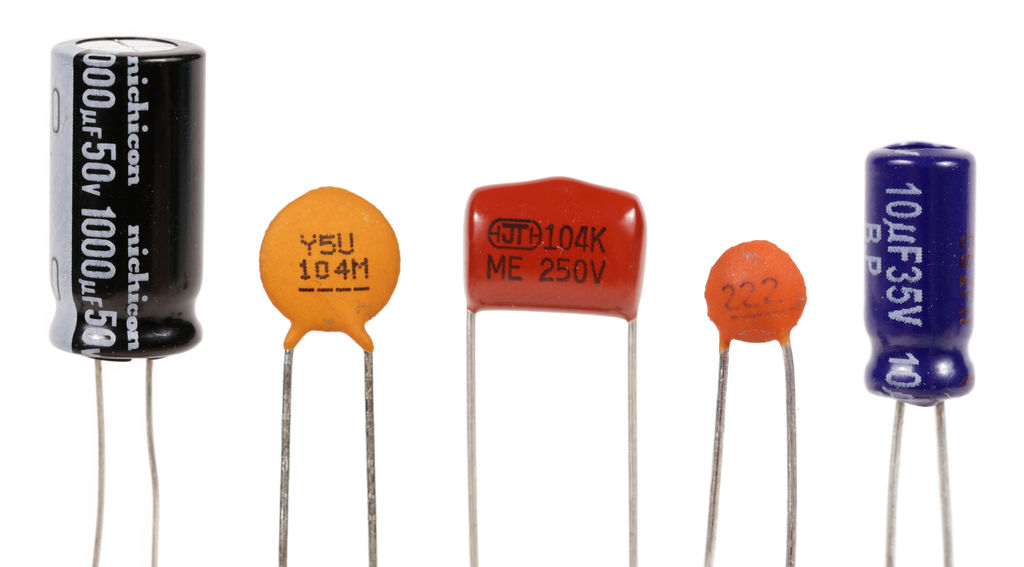
Capacitors are electronic components used in various circuits for various reasons. It has two terminals and comes in various shapes and sizes. The cylindrical shape is the most used one.
To properly define a capacitor, we can say that a capacitor is a passive component that can store electric charges upon the application of the right voltage.
By passive, I mean capacitors do not require any external voltage source to work properly, and they don’t have any gain.
Capacitance and its unit
We measure capacitors in terms of capacitance (C). Capacitance is the ability of a capacitor to store charges.
The SI (System International) unit of capacitance is Farad (F). It is named after the scientist Farad.
Typically, we measure capacitance in terms of milli Farad (mF) or micro Farad (uF).
Circuit symbol
Just like other circuit components, a capacitor has its unique circuit symbol which distinguishes it from other components.
Following is the circuit symbol of the capacitor:
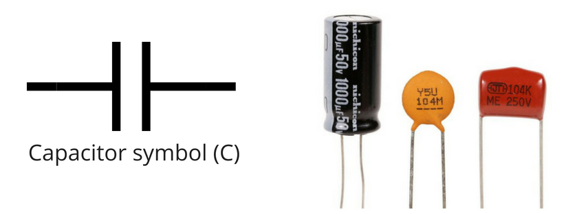
On the left is the symbol, while on the right we have some physical capacitors for your reference. You can see these capacitors are of different shapes, which we will get into the following section.
Why the symbol is chosen this way?
The reason is simple: a capacitor has two plates (foils). One plate is positive, and the other is negative. The two parallel lines just represent those plates.
Besides the parallel line are the external terminals. We connect the internal plates (foils) to other circuit components using these external terminals.
Basic principle of operation
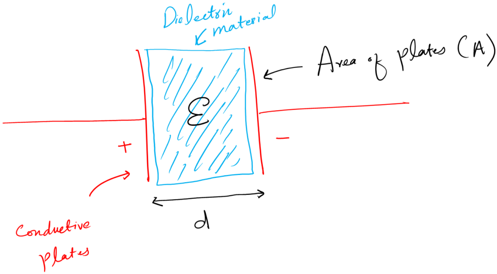
To understand how a capacitor works, let’s consider a simple parallel plate capacitor.
Imagine two conducting plates, one positively charged and the other negatively charged. The plates are separated by a dielectric material, such as air, ceramic, or plastic.
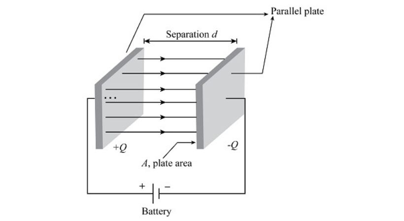
The positive plate gains an excess of positive charges (protons) and the negative plate gains an excess of negative charges (electrons) when a voltage is applied across the plates.
Between the plates, an electric field is produced.
Direct current (DC) cannot pass between the plates because the dielectric substance acts as an insulator between them.
On the other hand, it permits charge displacement, which causes an electric charge to build up on the plates.
The amount of charge stored on the plates of a capacitor is directly proportional to the applied voltage. The relationship is given by the equation
Q = CV
Where Q represents the charge stored, C is the capacitance of the capacitor, and V is the voltage across the plates.
That is how a capacitor stores charges on its plates or foils.
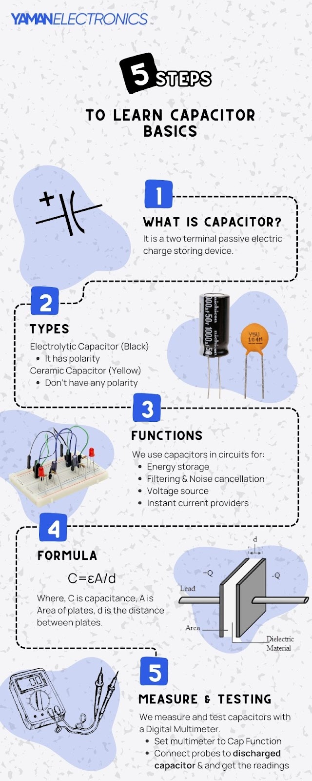
Type of Capacitors
There are mainly two types of capacitors.
- Electrolytic capacitor
- Ceramic capacitor
There are other types as well. But for a beginner, these two are very important to understand.
Electrolytic capacitor
It is the type of capacitor that has polarity. Polarity means that this capacitor has positive and negative terminals.
Following is the circuit symbol of an electrolytic capacitor:
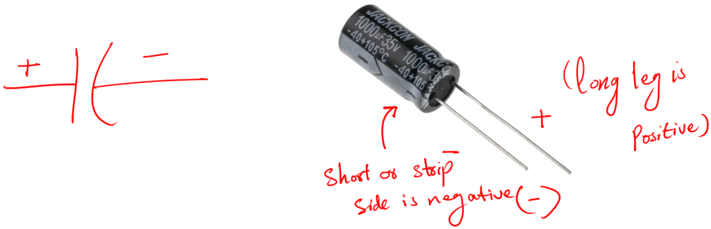
Remember the longer leg is the anode, the positive terminal. While the short one is the cathode, the negative terminal of your capacitor.
Care must be taken when using this capacitor in a circuit.
If you mistakenly connect the capacitor’s negative terminal to the voltage source’s positive terminal. The capacitor may not work and in some cases may get damaged.
We use these capacitors mostly at the front end of the circuit for noise cancelation and filtering.
Ceramic Capacitor
It is a type of capacitor with no polarity. You can connect them in a circuit in any orientation and they will work fine.
Following is the circuit symbol of a ceramic capacitor:
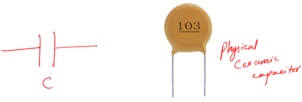
Usually, they are small. We don’t use them in the front end. We use it for small voltage and transient control.
The main difference between ceramic and electrolytic is that electrolytic capacitors are more like high power capacitors, while ceramic is lower end capacitors.
This is a short overview of various. Here is a detailed post on capacitor types and how to read the values of these capacitors. I encourage investing some time in understanding the types.
Concept of polarity
In electronics, you will encounter a lot of components with polarity. Meaning that you can not put those components in any orientation. You must put them in a specific orientation.
Electrolytic capacitors are one of those components.
Capacitance Basic Mathematics
The capacitance of a capacitor is determined by its physical characteristics, such as the area of its plates (A), the distance between the plates (d), and the properties of the dielectric material (ε).
Formula:
C=ε(A/d)
The permittivity (ε) is a property of the dielectric material and determines how well it can store electric field energy. It is a constant that varies for different materials.
Factors Affecting the Capacitance
Keeping the above capacitance formula in mind, we can say the area, distance, and permittivity are factors that affect the overall capacitance value.
Let’s see how.
1. Area
The capacitance is directly proportional to the area.
C ∝ A
The directly proportional means the larger the area of the plates, the higher will be the capacitance value because it will store more charges.
Increasing the plate area increases the number of charges that can accumulate on the plates, thus increasing the capacitance.
2. Distance between the plates
The distance between the plates also influences the capacitance of the capacitor. The capacitance of a capacitor is inversely proportional to the distance between its plates.
C ∝ 1/d
The electric field between the plates gets stronger as the distance between them reduces. More charge builds up on the plates as a result, increasing capacitance.
In contrast, the capacitance decreases as the distance between the plates increases.
3. Dielectric Material
The capacitance is also directly related to the permittivity of the dielectric material.
C ∝ ε
The greater the permittivity, the greater the capacitance, and the lesser the permittivity, the lesser the capacitance.
Some material offers less opposition to the electric current, so more charges will be stored. Materials like ceramic, paper, plastic, and electrolytes have higher permittivity compared to air or vacuum.
4. Fun Activity
The above mathematics seems dry. To better understand this concept, here is a fun activity.
Please use this online capacitor simulation app. It helps you visually see what happens when you play with the plate areas, the distance between them, and so much more.
Capacitor Functions
There are many applications of capacitors. It depends on what you want to achieve with it. It also depends on what circuit (electrical or electronics) you are working with. What are the requirements of a circuit, and much more?
Following are functions of capacitors that you can take advantage of in your next project.
1. Storing electric charges
I should say it is not like a function or application but more like the property of a capacitor that stores electrical energy between its plates. All other functions of a capacitor depend on this property.
2. Noise cancelation
We don’t want noise in a circuit at all, but we can’t eliminate it. We can do our best to reduce it to acceptable levels depending on the circuit’s output requirements. To eliminate noise, we use capacitors in our circuits.
3. Circuit safety
A glitch in a circuit may occur from various other reasons and sources. As designers, it is our job to design circuits that can eliminate such glitches to a maximum acceptable level. And capacitor is our guy for such design.
4. Instant current provider
Sometimes we need a source that can give us high current in a very short time, like instantaneous. In such a situation, capacitors are very useful. They charge and discharge in milliseconds.
This was some functions, but it doesn’t stop here. Here is a detailed post on capacitor functions that walks you through all the functions of capacitors in circuits.
Capacitor Safety Considerations
Working with capacitors requires certain safety precautions to prevent electrical hazards. Here are some important safety precautions to consider when working with capacitors:
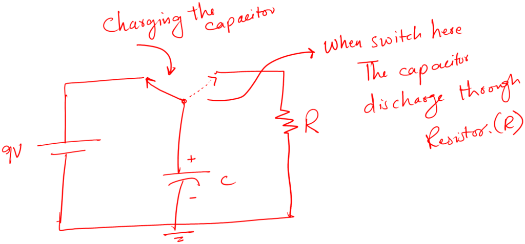
1. Discharge Capacitor
To prevent electric shock, discharging the capacitor is essential. You can use a resistor (with a high enough resistance to prevent a sudden discharge) connected across the terminals of the capacitor.
Additionally, there are specialized discharge instruments made for this use, such as a discharge probe that enables safe discharge without coming into contact with the terminals.
It is important to consider the discharging of the capacitor if it is connected to the circuit while you are about to examine it.
2. Turn off power sources
If you want to work with the capacitor which is already connected to the circuit, you have to turn off the power source to avoid any accidental injuries.
3. Use Insulated Tools
It is essential to use tools that do not conduct electricity. Insulated tools, such as screwdrivers with insulated handles or pliers with rubber grips, help prevent electrical conductivity.
For example, you are replacing a capacitor and forget about turning off the power source. If you use conductive tools, it will cause shock.
For adjusting or connecting a capacitor in a circuit, using insulated tools reduces the risk of accidental electrical contact.
4. Understand Polarity
It’s crucial to follow these markings to avoid damaging the capacitor or the circuit. If you’re replacing an electrolytic capacitor, the negative terminal should be correctly identified and connected according to the circuit’s requirements.
5. Avoid overheating
Every capacitor has maximum operating voltage and current. If the applied voltage exceeds this limit, it will cause overheating, leading to failure or even rupture.
To avoid overheating while building a circuit, make sure the capacitors’ voltage and current ratings either meet or surpass the circuit’s specifications.
Capacitor Rating
Capacitor rating refers to various specifications and parameters used to describe capacitor limitations and characteristics. It helps in selecting the right capacitor for a specific application and ensuring its proper functioning within a circuit.
The capacitor rating includes
- Capacitance
- voltage rating
- Tolerance
- Polarity
- Temperature coefficient
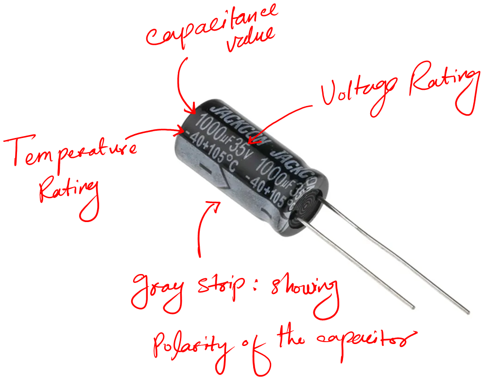
We know what capacitance and polarity mean. Let me quickly explain the new terms below:
- Voltage rating (expressed in V) is the maximum voltage a capacitor can withstand without risk of damage.
- Tolerance (indicated as a percentage) represents the maximum allowable deviation from the labeled capacitance value.
- Temperature rating describes the maximum temperature within which the capacitor can be operated without damaging it.
You can learn in detail about capacitor rating in this article. Ratings are very important when working with physical capacitors.
Measurements
We can measure the capacitance of a capacitor using various methods like:
- Using a multimeter
- Using a capacitance meter
- Using an ESR meter
- Using an LCR meter
- Using a component tester
All methods give the exact value of the capacitor. So, no matter which meter you have access to, you can use it.
For a beginner, a digital multimeter is best. For more accurate readings, LCR and capacitance meters are used. For capacitor testing, an ESR meter is used.
Follow the following steps to measure the capacitance using a digital multimeter:
- Take your auto range digital multimeter and connect the probes
- Set the multimeter to capacitance mode (F)
- For the electrolytic capacitor: connect the COM probe to the negative leg of your capacitor and the red probe to the positive leg.
- For ceramic, polarity does not matter. Connect the multimeter any way you like.
- See the results on the multimeter screen – it is just that simple.
Your multimeter must have a capacitance feature for the above method to work properly.
The good news is when it comes to capacitors. The capacitance value is written on its body. You can read this value without having a multimeter.
Talking about methods in detail needs a dedicated article. Here is the detailed post on Capacitor measurements for further study.
Capacitor testing
Every electronic component upon use gets burned or stops working. There may be various reasons why a component stops working and becomes bad.
It may be due to overvoltage, overcurrent, or heat. The point is, that it is normal to have bad components sometimes.
Capacitors are not different. They get burned, damaged, and stop working.
So how to test them, to be sure that we are working with a good capacitor?
Well, there are a few methods that we can use to find out if a capacitor is bad. If the capacitor is solo and not inside the circuit we use:
- Digital multimeter with capacitance measuring capability.
- We connect the capacitor to the meter and measure its value
- If the values match the value written on the body cover of the capacitor, we say we have a good capacitor
- Else we have a bad capacitor.
If the capacitor is inside the circuit board, then we use the ESR meter. ESR means equivalent series resistance of a capacitor. This value increases if the capacitor is bad.
Here are detailed posts on capacitor testing and in-circuit capacitor testing for your further learning.
Capacitor hunt activity
At this point, I think you have enough information about the capacitors. I believe that now you should be able to hunt or find a physical capacitor on any circuit board.
Why not test your knowledge?
Don’t worry! I am sure you will find a capacitor in the following circuit board.
Find an Electrolytic capacitor in the following circuit prototype:
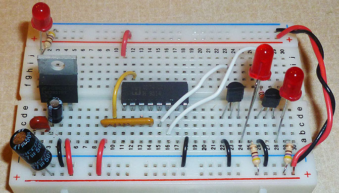
Please share your answers in the comment section. It will be fun to read your experience.
Conclusion
A capacitor is the fundamental component in electronics that can store electrical energy. It consists of two parallel plates and a dielectric substance such as air or plastic is used to separate them.
We measure the value of a capacitor in terms of capacitance (C) which is the ability of a capacitor to store charges. The SI unit of capacitance is Farad (F).
The capacitance of the capacitor is affected by some factors such as the surface area of plates, the distance between them, and the dielectric material used between them.
Different methods are used to measure the capacitance. The multimeter, ESR, LCR, and capacitor meter are the different tools that can be used to measure capacitance.
The capacitor has two main types. One is electrolytic, which is polarity-dependent. The other one is ceramic, which is polarity-independent.
With that said, we use capacitors for the following main reasons:
- To store charges
- Noise cancelation
- As a filter
- Circuit safety
- Instant current provider
So that is it. That I have for you to share about capacitors in electronics engineering.
I hope you enjoyed it.
Thank you & I see you around.
Other useful posts:
- Get Started with Electronics
- Basic electronics for beginners
- Electronics Circuit Prototyping & it’s Important
- Electronics Components Basics
Great article, not only this one, but other too. I learned new things from it, even I thought there won’t be anything new to me.
I just have 1 question about discharging capacitor s before measuring them. English isn’t my first language, so it may be I misunderstand it
“Remember to always discharge a capacitor before testing it with any device. What happens is —– if you discharge the capacitor, it might damage —- your measuring device by providing high voltages and current flow through it.”
Shouldn’t it be “if you —– don’t discharge —– the capacitor” in the above fragment (it is below m328 tester)?
Thank you for your website, I’m going to dig deeper to find more information about electronics, as it is provided in an easy way to understand it!
You are right. Thank you for pointing that out.