
I think the end goal of electronics is to learn electronic circuits with a deep understanding
Because without the proper understanding of electronic circuits one may not be able to build amazing products and solve real time problems.
The question is what is an electronic circuit and how to learn about it in the most effective way.
An electronic circuit is a careful combination of electronic components that we arrange and put together in a specific way to make a complete circuit.
Now, this complete circuit may be intended for learning, or it could be a solution to a big problem.
If this short introduction has got your attention. I am sure you will enjoy the rest of this article as well.
Hi, I am Abbas. In the rest of this article, I will share in great detail what is an electronics circuit, what is its core function, what we need to make working circuits, tools for designing a circuit, testing a circuit, types of circuits, and so much more.
Everything will be intended for beginners so don’t worry there will be no heavy mathematics and or such advanced concepts.
I am not perfect, nor this article is going to be. This is just my limited knowledge try to help you somehow.
I hope you will enjoy it.
Learn electronic circuits for beginners
Have you ever opened any electronic device? If yes then you may have noticed a green board in it. This green board is actually an electronic circuit board.
This green board is responsible for the functions of that product or device. For example, the motherboard of your PC and laptop that does all the amazing things on the screen is actually an electronic circuit.
I can talk on the green board, but I think you got the idea that an electronic circuit is like the backbone of any electronics product you see around you.
Now let see in detail what is an electronic circuit and how we can properly define it.
The proper definition of electronic circuit
As I am writing this article keeping in mind a complete beginner person. So I will explain everything from the core beginning so that you can have a deep understanding.
Alright!
Electronics is the study of the flow of charges in semiconductor devices. These semiconductor devices are made of semiconductor materials such as Silicon and Germanium.
Now, semiconductor devices that we study in electronics are the following:
- Diodes
- Transistors
- LEDs
- Thyristors
- MOSFETs
- FETs
- IGBTs
These devices are also called electronic components. Electronics components are a more popular term, and you will see it a lot, but this term just means semiconductor devices that we use in electronics.
Other than the above electronics components we also have the following electrical component as well.
- Resistors
- Capacitors
- Inductors
- Transformers
- Relays
Now we got the idea about various components. Now it is the time to play with them and make some circuits.
The electronics and electrical components combined help us make and design amazing electronic circuits. The combination of these components determines the behavior and purpose of a circuit.
The same resistors, diodes, and capacitors connected in some way may make a power supply circuit. But the same components with different arrangements may end in a whole different circuit.
An electronic circuit is a careful arrangement of various components that serve a specific task. For example, the electronic circuit of your PC is to help you play games, connect to the internet, do your work, and so much so.
Following is the example of the circuit board for your reference.
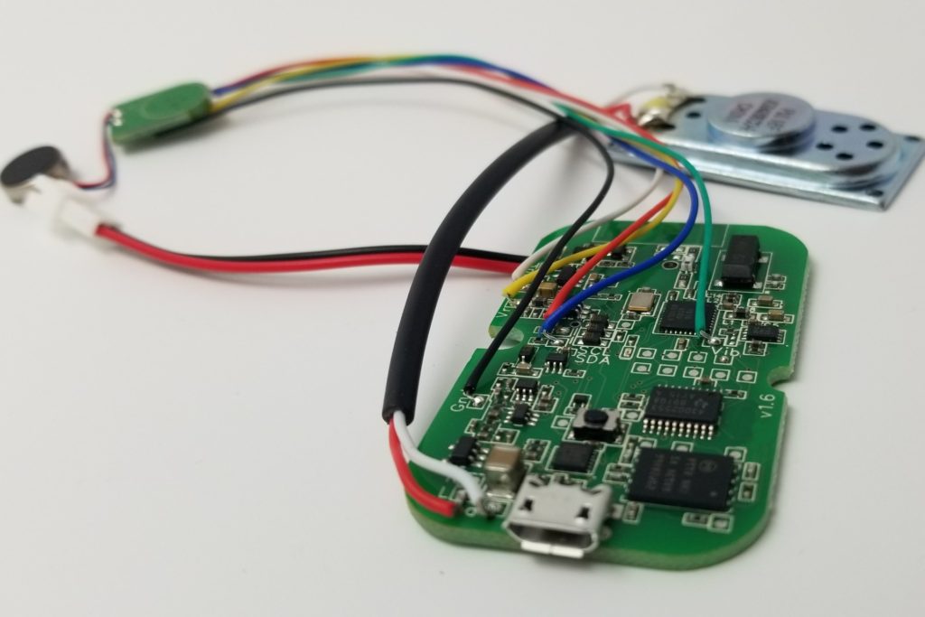
We arrange the components to make a PC or laptop circuit. We arrange them to make a toy. We arrange them to serve space rockets. We arrange them to help us communicate with the outer satellites and the list goes on.
In a more simple way:
An electronic circuit is a careful combination of various components such as diodes, resistors, and capacitors by connecting wires.
I hope you got the idea of an electronic circuit.
Alright! Moving on to the types of circuits.
Types of electronic circuit
There are so many types of electronic circuits. But I think explaining them in detail right now is not a good idea. So I will give you the names and a brief introduction.
Following are the two main types of circuits.
a. Analog circuits
You know, if we pay attention to our surroundings we will find out that everything is continuous. Like the sounds we hear are continuous in nature.
Similarly, voltage signals are continuous, current flows in continuous nature, and so on.
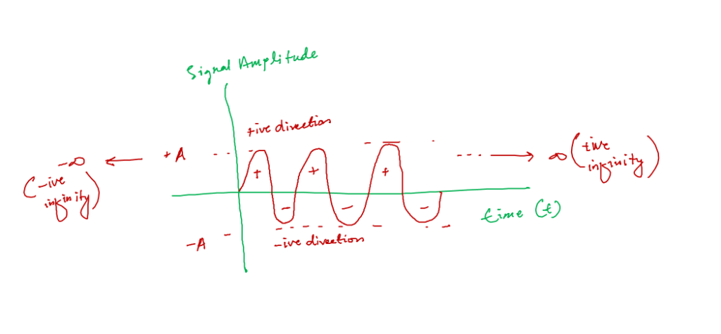
So the type of electronics that deal with continuous quantities and signals is called Analog Electronics. And the circuit that we design to work with continuous signals is called Analog Circuit.
b. Digital circuit
Analog electronics require a high bandwidth which is very expensive from the manufacturing point of view. So we convert analog signals to digital signals to decrease the bandwidth requirements.
Also, digital signals are more prone to nose compared with analog signals.
Now, the circuits that deal with digital signals are called digital circuits. They are everywhere these days because of their highly promising features.
Open circuits
Let’s talk about the most common term used in electronic circuits, i.e., open circuits.
Any circuit must make a complete loop, else the circuit would be an open circuit or incomplete circuit.
In simple language, an incomplete circuit is called an open circuit. Or more technically speaking any two electrical points on a board or circuit that offer infinite electrical resistance, we call it an open circuit.
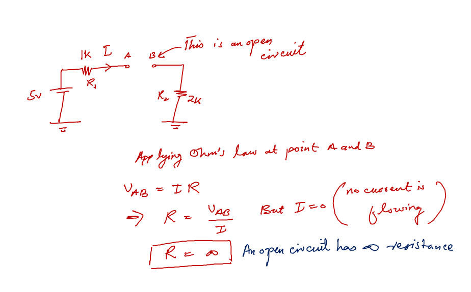
By applying Ohm’s law we can clearly see, that any circuit points that offer very large (infinite) resistance will be treated as open circuit points. The interesting facts about open circuits are:
- There can be any voltage value across the points i.e. for example in the above picture point A and B have any value voltage.
- No current flows through the open circuit whatsoever.
Short circuits
Opposite to the open circuit, there is a short circuit. Technically speaking, any two electrical points on a board or circuit that offer zero resistance is referred to as a short circuit.
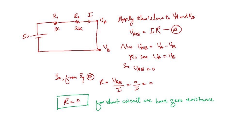
When we apply Ohm’s law to the short circuit we end up with zero resistance. The following are basic things you should keep in mind about a short circuit.
- The voltage difference across a short circuit is always zero
- Any amount of current can flow into a short circuit. And this is the reason we often hear a building catch fire because of an electrical short circuit.
Now we combine two components by shorting their terminal to one another, this is good and this is how we connect components. But if we short the connection of the two terminals of the same device we might end up damaging that device.
Designing an electronics circuit
We have discussed the proper definition of electronic circuits and seen some useful types of circuits.
Now let’s talk about how to design electronic circuits from scratch as a complete beginner.
a. Idea
First of all, you need to have an idea of what problem you want to solve with an electronics circuit. This is the hard part when you are a startup and trying to solve a big problem.
But for beginners, you can look for some inspiration. Or at your earlier stages, I would recommend just starting with a step by step project. A project that will lead you from start to end.
Once you got some experience working with guided projects. Start working on some small projects of your desire. And then slowly move toward your own projects.
For example, you are at home, and you got an idea of how to remotely control your home lights from anywhere in the world. Start by controlling one bulb in your room, then work on your entire room, and then scale it to your entire home.
b. Circuit simulations
After you decided what you want to build it is time to do some head and trial solutions. The best way to do this is to use circuit simulation software.
Circuit simulation software is a tool that we use to design and test our circuits without physically implementing them. These simulation software programs are available for offline computer installation as well as for online use as well.
With circuit simulation, we test the various circuit designs that we think are good and see the results. Circuit simulation is kinda the research part of a whole circuit design process.
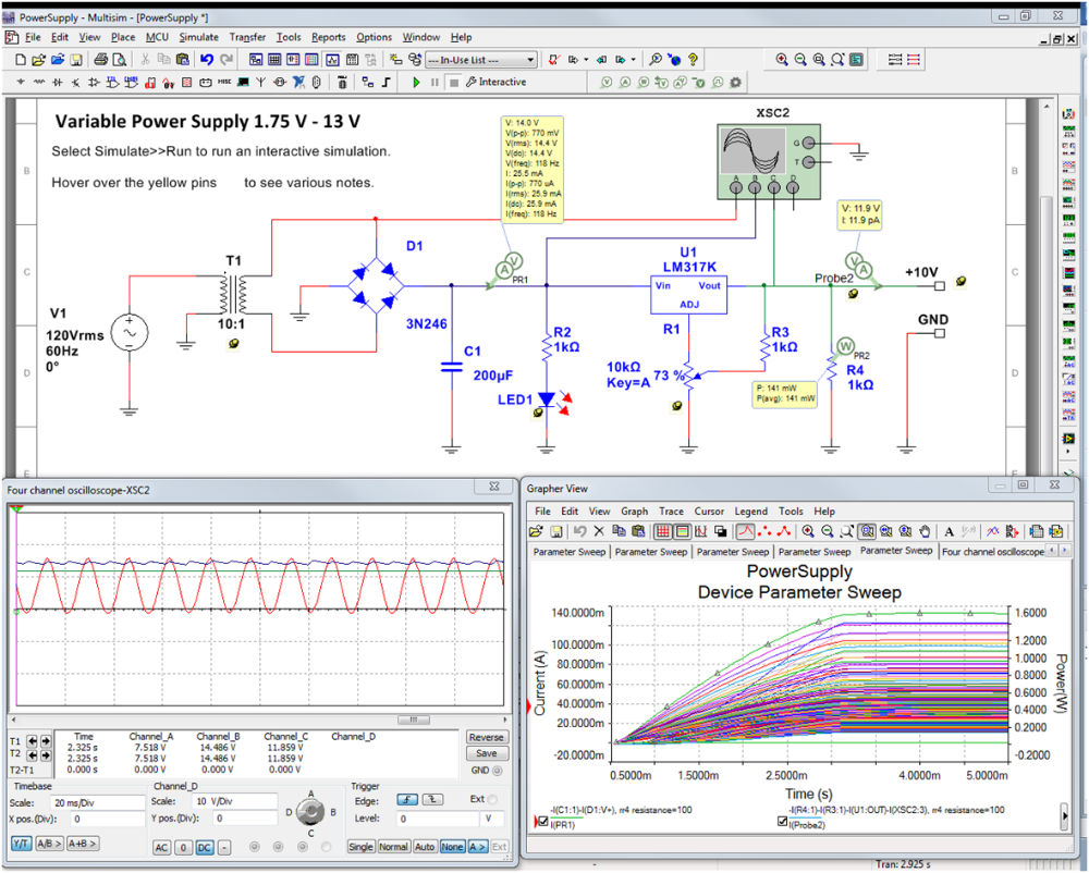
We research different circuits, we try our own imagination, and try to come up with a circuit that will get the job done.
For complete beginners working with DIY projects, this stage will not make sense to you. As you are already given a circuit diagram to replicate. But remember this circuit diagram is prepared using circuit simulation software.
c. Circuit prototyping
After we come up with our final solution trying with different simulations. It is time to physically implement the circuit to verify the simulation results. You know the process to learn electronic circuits is fun when it comes to this stage, the circuit prototyping.
Circuit prototyping is a process in which we make our circuit on a solderless breadboard to verify our simulation circuit and its results with a real time circuit.
In circuit prototyping, we use breadboard which is a solderless device. This, make us able to make a temporary circuit without permanently soldering the components together.
Following is an example of a circuit prototype.
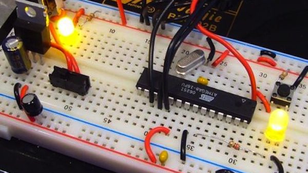
You know, circuit simulation has its limitation as well as breadboard (it introduces parasitic R, L, and C, especially for RF circuits.) has its own limitation. But both give us a pretty close real evaluation of how our circuit or project would perform in practical scenarios.
d. PCB Design
Circuit prototypes help us to verify the results and give us a clear vision of if the circuit is going to work in real time situations or not.
When we are satisfied with the results. It’s time to make a PCB for the circuit. PCB is short for printed circuit boards. These are the green boards you see in almost every product these days.
Following is the example of a PCB board:
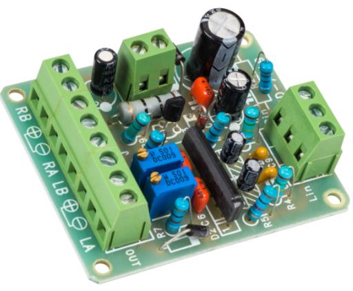
As we discussed there are softwares for circuit design. Similarly, there are PCB design softwares as well. We design the PCB in those softwares, generate the required files and send them to PCB manufacturers for batch production.
e. Batch production
This is the last stage of any electronic circuit design. In this stage, we generate files from the PCB software called the Gerber files.
First, we make a PCB prototype to again verify the results. We sent out this PCB for CE and FCC testing as well. Because when the design PCB doesn’t pass these tests we will not be allowed to sell the products with this circuit board.
After clearing all the tests, and we are fully satisfied with everything. It is time for batch manufacturing.
Above was the process of designing an electronic circuit. I try to keep everything as simple as possible. I hope you got my points there. Keep in mind that you can’t excel in all the processes of electronic circuit design. Choose the part that you like the most and be an expert in it.
Tools to work with electronic circuits
You know to work with electronic circuits we should have a proper lab setting. This lab should not be equipped with all the advanced devices at the beginner level. But it must have the following tools to test and analyze the circuits.
You saw the above circuit prototypes. These circuit prototypes are only possible if we have the right tools and devices in our lab.
a. Multimeter
Let’s start with our first lab tool to learn electronic circuits, called the multimeter.
You know, a multimeter is a very fundamental tool when it comes to electronics. It is like the go to device when we want to measure various quantities. It helps us to measure the resistances of a resistor, voltages, current, and so much more.
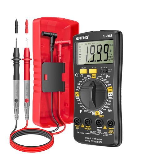
Briefly, the multimeter is used to measure the following. Don’t worry if you are a complete beginner and don’t know about the following just yet. Just remember the multimeter as a measuring tool.
- Resistance of a resistor that we want to use in our circuit
- The capacitance of a capacitor
- AC voltage and currents (from milli range to high values)
- DC voltages and currents
- Circuit continuity – to find out about the open circuits.
- Diode testing
- Transistor testing
- Frequency measurements
- The inductance of an inductor
- and much more
You can see for yourself that this little device has so much importance when it comes to electronic circuits. I think if you don’t have this device you will not be able to learn electronic circuits effectively possible.
Now to get yourself a decent multimeter, the following post will help you in getting in your own first multimeter.
b. Breadboard
The next tool is the breadboard. A breadboard is a tool we use all the time when making any circuit prototype. It is like a go-to tool when it comes to building physical circuits.
Remember, we use a breadboard to make circuits, but these circuits are prototypes.
Prototype circuits are those circuits that we use to test our results before sending out our design to the manufacturing house for high volume production.
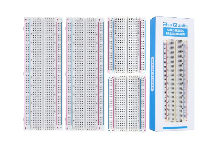
Breadboards come in various shapes and sizes. But every breadboard has rows and columns. We put our components in these rows and columns, depending on our design.
Also, we connect various components through connecting wires. In the end, we have a working prototype of a circuit (if everything goes the precise way it is supposed to be).
c. Connecting wires
As the name is explaining itself effectively. Connecting wires are copper wires which help us connect various electronic components together in the required manner to build electronic circuits.
Connecting wires come in various shapes, sizes, and lengths. But they all serve the main above application.
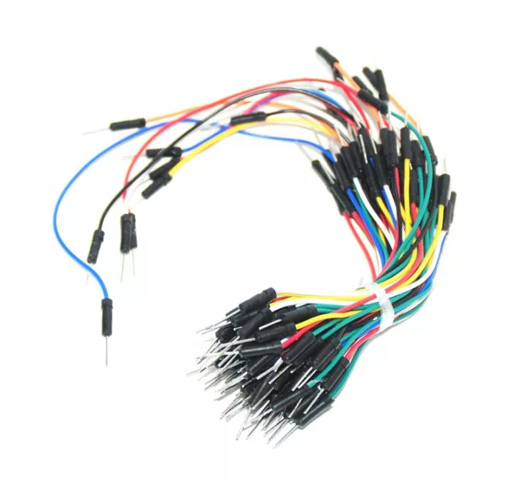
The above wires are perfect to work with a breadboard. But it is not necessary that you have to use them in every circuit.
d. Power supply
The next device that we would need for our basic lab is the power supply. No matter what type of circuit or project you work on. You require a power source to power them up.
Power supply just helps us achieve the above in an efficient and safe way.
You can consider a power supply as an energy supply source for our electronics projects and circuits. Without energy there will be no working circuits, that’s simple.
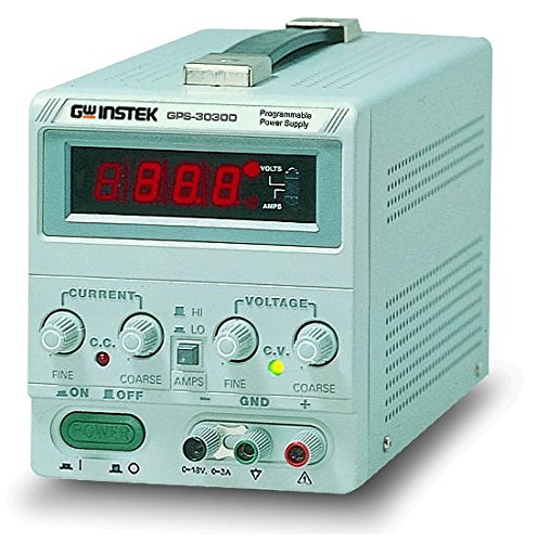
And that is why a decent power supply is a must have tool, device, or equipment for an electronics guy’s work environment.
e. Component tester
When you are a beginner and you got one project you are really excited about. At such a moment you really enjoy your time.
You have a few components to work with.
But imagine if you are working on a bigger project. Or electronics repair is your job or the field you want to excel in. Then working with a lot of electronic components will be a bigger challenge for you.
Because it takes time to check each component whether is good or bad. To handle this we need to have one of the best electronics tools called the components tester.
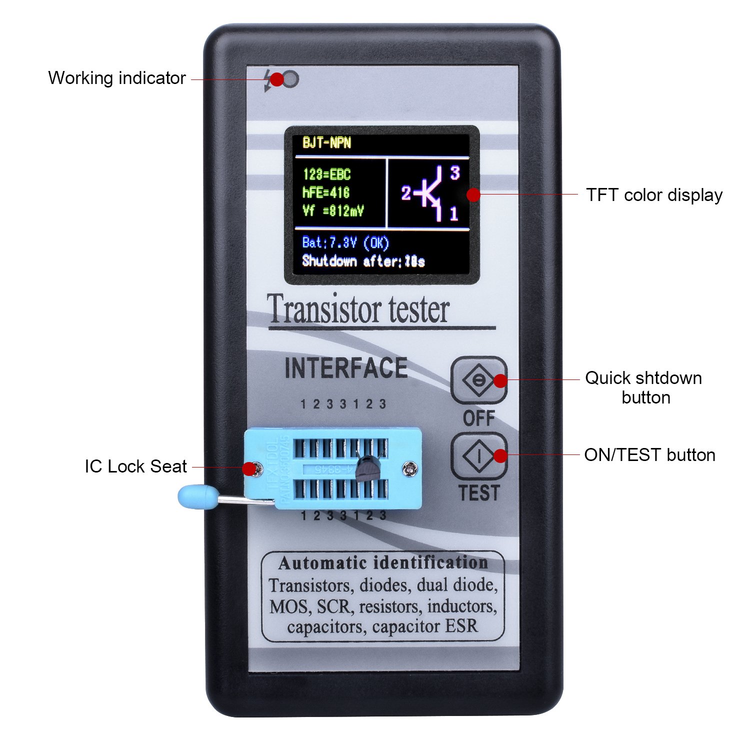
People also call it a transistor tester. But both names refer to the same device.
You just simply put any electronic component in this device, and it tells you right away if the component is good or bad. It also gives you its respective value as well, decreasing your multimeter usage as well.
f. Oscilloscope
The next device is the oscilloscope. This device helps us visually analyze the various circuit signals.
As we have discussed above, circuits are mostly of two types, i.e., analog and digital circuits. Analog circuit works with continuous signals while digital circuits work best with digital signals.
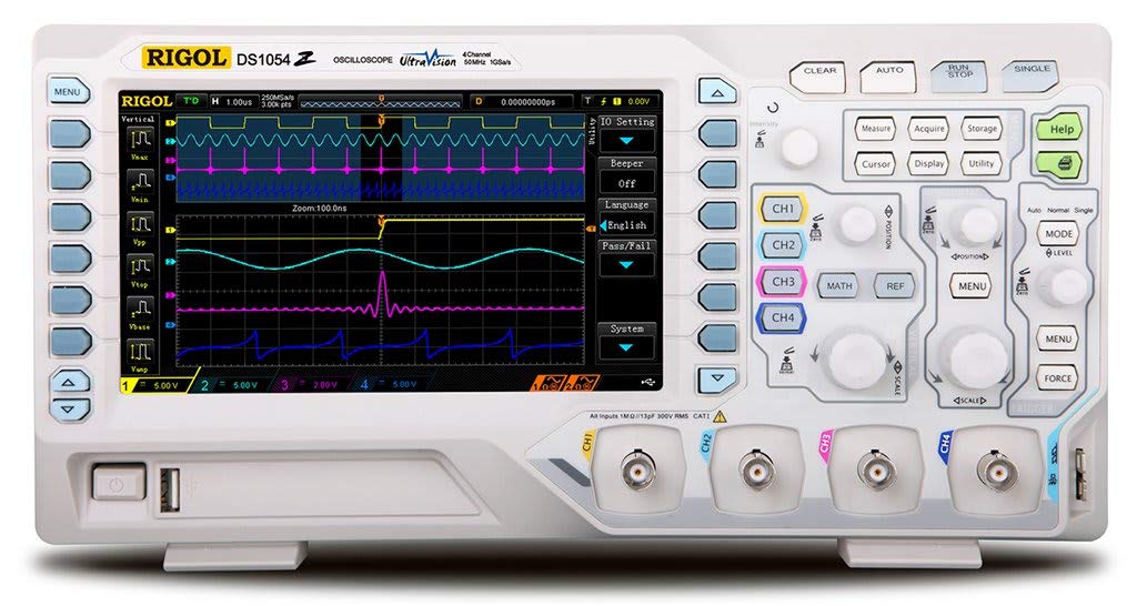
To study the behavior of both circuits at the output side we need a tool to visually help us see the signal, and analyze and measure its various parameters.
The tool which helps us achieve the above is called an oscilloscope. We use this tool to draw the graphs, perform mathematical functions on them, and take informed decisions about the circuit.
g. Component kits
This one is very important in my opinion. Like if you don’t have proper components then how are you going to build circuits with. This just does not make any sense to me.
By electronics component tool kit, I mean a proper selection of various electronics components packed in well-organized boxes or bags.
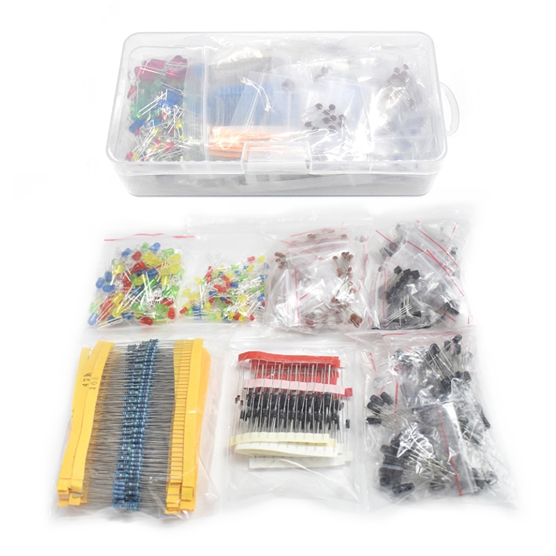
The most common use components are:
- Resistors
- Capacitors
- LEDs
- Diodes
- Transistors
- Potentiometers
- Buzzers
Of course, there are a lot of other components as well. But as a beginner, you will most probably be just working with the above ones.
Circuit testing and troubleshooting
One of the amazing things to learn about electronic circuits is to test old or new circuits, and if they are not working properly try to troubleshoot them.
Circuit testing is to verify the output at each stage of a circuit. By verifying I mean to see if the circuit is giving you the results that it is supposed to give or not.
Troubleshooting is something different. In this, we are looking to spot out what causing the issues in the circuit. This task is tedious and takes a lot of time and experience to troubleshoot various electronic circuits.
Conclusion
To learn electronic circuits for beginners, the first thing you should have is willpower. Because without willpower it is not possible to do anything and learning about electronic circuits is no different.
When you have the willpower then I believe circuits are a fun and exciting field to join.
To properly define an electronic circuit I can say, an electronic circuit is a proper combination of various electronic components to perform a specific task.
There are two main types of circuits called analog and digital circuits. Other than these two there are open, short, parallel, and series circuits as well.
So that is it. That is all I have for you about learning electronic circuits. I hope you enjoyed it.
Thank you and have grateful life.
Other useful posts:
- 15 Best Electronics Component Kits For Beginners
- 21 Best electronics tools & equipment for beginners
- Can I learn electronics on my own? (Simple Answer)
- Easily Get Started with Electronics (Step by Step Guide)