
A resistor is the most used component in almost every electronics circuit. You will find its application from DIY circuits and projects to commercial products.
In short, you have to learn about the resistor basics if you want to make a career in electronics or to understand the digital electronics world in which we are living.
Basically, a resistor is a two terminals passive electronic component that we use in our circuits for current limitation, voltage division, positive feedback, and much more.
We measure the resistance value in Ohms. And the tool we use to measure and test resistors is called the multimeter and a component tester. These tools just give away the resistance value of our resistor in no time.
Hi, I am Abbas. If this short introduction has got your attention then I am pretty positive you will enjoy the rest of this article.
In the rest of this article, I will share some basics of the resistor, what is a resistor, what it does in circuits, some important circuit design accepts, how to measure it, and test it before placing it on real circuit boards, and so much more.
I am not perfect nor this article is going to be. This is just my limited knowledge try to help you somehow.
I hope you will enjoy it.
Resistor basics & testing
If we try to understand the concept of a resistor in a simple way. It should be like this. You know everything opposes a new change. Like we humans oppose new changes in our lives, we oppose adopting new habits and thought patterns. This resistance is like in nature of everything.
The same goes for electronics conductors. The conductor resists when we want to change them by applying a voltage across it. This voltage creates a current flow that the conductor really doesn’t like and thus opposes it.
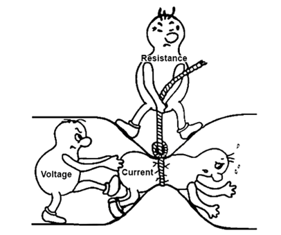
The opposition to the current flow is actually the resistance. Since this phenomenon was discovered by Ohm that is why we measure this resistance in Ohms (in the honor of his contribution).
Now, this resistance is really important, and we can use them for many useful situations. For example, if there were no resistance then an infinite amount of current would flow, and it will burn and damage everything, and no electronics would be possible.
We understood the importance of the resistance and created a separate component in our labs called the resistor which provides resistance to flow of current flow.
A resistor is a two terminal passive device that opposes the flow of current through it.
Resistor definition
It is basically made of such materials that provide opposition to the current flow.
Now you may think that we were talking about conductor resistance now we have made our own component. And you are right. Conductors offer opposition, but it is very low, and we need our own component with our own resistance value (designed to our specific needs and requirements).
In short, we learned the phenomenon of resistance from conductors. But putting a wire conductor in real time circuit is not practical. Thus, we designed our own component called the resistor that offers resistance according to our own specifications. And we can put them in our circuit effectively.
I guess you got a simple idea of a resistor. Let’s move on with our topic.
Circuit symbol of a resistor
In electronics, every component has its circuit symbol. A circuit symbol helps us draw the circuit on paper for our analysis and design. Also, with the circuit symbol, we can simply design our circuit in simulation software.
Following is the circuit symbol of a resistor and some actual physical resistors.
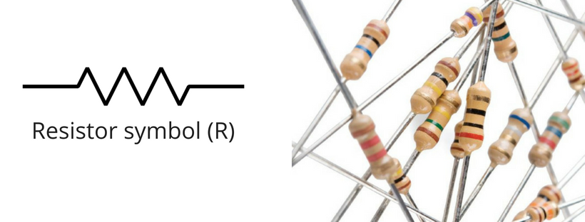
You see, the symbol is zig zag. It is chosen this way to illustrate that it is a hard path for current to flow.
Let’s see how to identify a resistor on real time circuit board. Because this is our aim to use a resistor in our circuit for the solution we face.
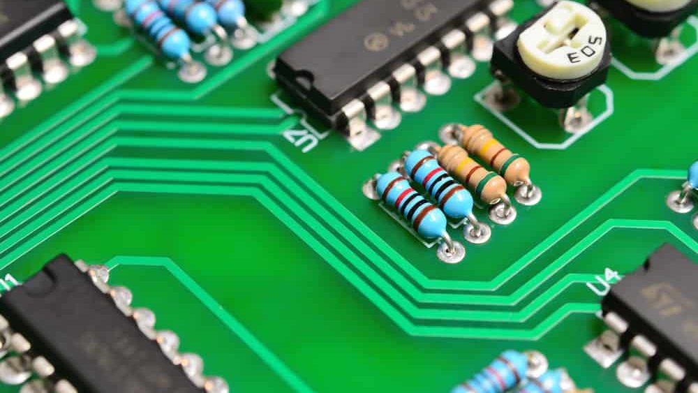
Now you are capable to identify resistors in a circuit board. People miss this thing and focus too much on theory. The theory is good but here we are focused on practical things and aspects of electronics resistors.
Measuring the resistance value
The next thing is how we can measure the resistance value of any resistor. The answer is simple. We can do this by the following proven methods:
- By color code
- Using a digital multimeter
- Using a component tester
Let’s explore this method one by one.
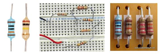
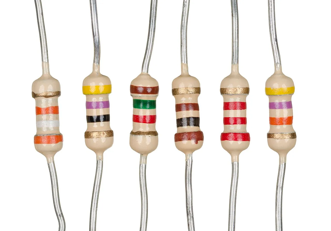
Color code
This method requires us to read the code on the resistor body. If you pay attention to the resistor above you will see that there are color stripes on each resistor. These stripes are actually the color code.
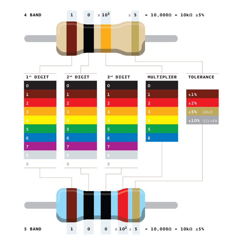
By reading this color code you can actually tell the value of any resistor. It is useful when we test our resistor.
Reading a color is easy and straightforward. The first color in the stripe is your first digit, the second color is the second digit, the third color is 10 power, and the last one is the tolerance value.
In practice, we usually don’t prefer this method as it is very time consuming. But I shared it for those who are students and learning about resistor basics for their semester course or something like that.
Using a multimeter
This is a practical way to measure the value of your given resistor. To do this method we first need to know what is multimeter.
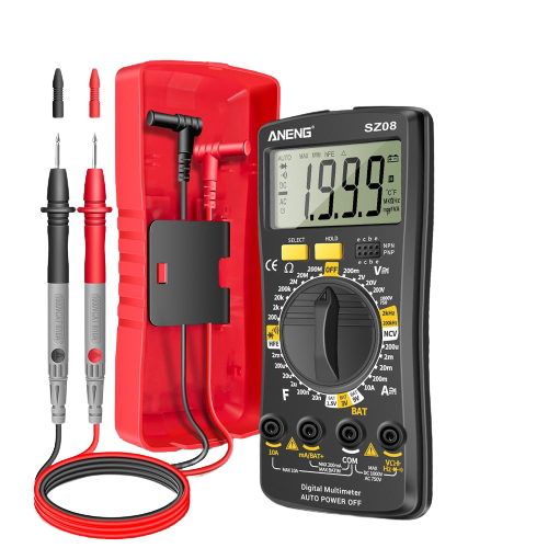
A multimeter is an electronics measuring device that we use to measure the following values:
- Voltages
- Current
- Resistances
- Capacitance
- Frequency
- Inductance
- Continuity
- Diode testing
I am not going into detail about how to use a multimeter to measure resistance as this is not our topic. I share it, so you know about the different methods.
Using a component tester
This method is very interesting and very easy to implement. For this method, you need a component testing device.
A component tester is a device like the above multimeter with the capability to test and identify various electronics components. Following is one of the best component testers out there on the market. It is called the M328 tester.
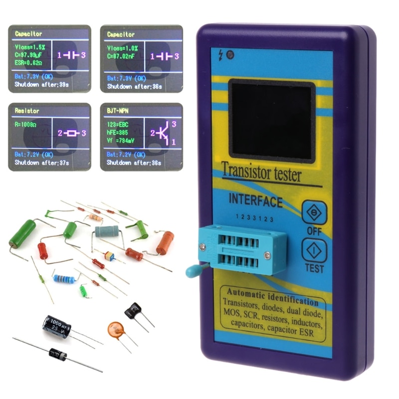
It is user friendly and can measure the resistance value of any resistor in no time. Just place the resistor in it, press the test button, and get the results on the screen. It is just that simple.
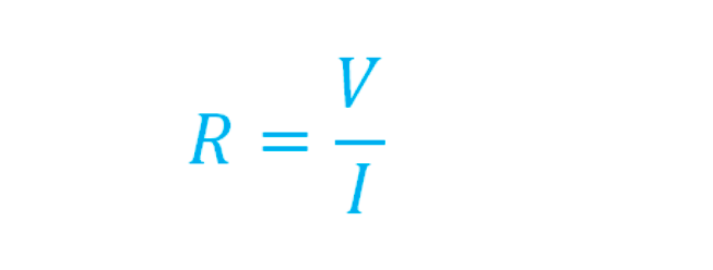
Simple resistor formula
At the beginner level, we can derive the resistance formula from Ohm’s Law. But as you will study advanced electronics you will see this formula is not sufficient, and it is limited to only linear resistors.
Following is the simple resistance formula:
Types of resistors
There are mainly two types of resistors we use in most of our electronics projects. They are the following:
- Fixed value resistor
- Variable values resistor (Potentiometer)
Let’s talk in detail about these guys.
Fixed value resistor
As the name suggests these are the resistors that have a fixed resistance value. And this value doesn’t change in any circumstances. If it does then it would mean your resistor has been damaged and need to be replaced.
Following are the fixed values resistors:
You will identify them as they are referred to as 1K Ohm, 10KOhm resistor, etc.
Variable resistors
The value of the resistor changes that is why they are called variable resistors. We need variable resistance in various electronics projects like sensing and voltage division projects.
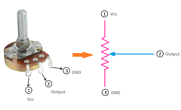
You see, this resistor has three terminals. 1 and 3 are fixed and 2 can slide over which is responsible for variable resistance values.
Why we need resistors in circuits
This is a very important question in learning resistor basics. Like it is really necessary for you to understand why you need a resistor in our circuit in the first place.
Following are the few reasons that I think make a resistor so much important in our electronics circuits.
Current Limiter
The resistance value of the resistor determines the amount of current that can easily flow through the resistor to the rest of the component or circuit.
Hence, the value of the resistor for a fixed resistor is fixed, which means that the amount of current is fixed.
So, if you don’t want a current amount to exceed a certain value in your circuit. Then use a resistor with a resistance value respective accordingly using Ohm’s Law.
Voltage Division
Sometimes we require multiple voltage levels in one signal circuit. The issue is, that we can not put different values’ power sources.
If we do the above, you can imagine our circuits and product will be bulky, heavy, and with limited styling. And most importantly, very efficient in the long run.
So, we use resistors in voltage divider configuration to achieve different voltage levels according to the requirements of our circuit.
Remember, voltage division is best used for small values and powering small devices. You should not expect it to use for heavy currents, as it is not designed for this purpose.
Voltage referencing
The voltage reference is a pre-set constant value to which we compare our other values, or use it as a state.
The voltage reference is a very important concept and plays a key role in digital circuits.
We use the above voltage division circuits to make voltage levels which we use for reference purposes in our circuits.
Feedback
Feedback term is mostly used when we are working with operational amplifiers, shortly op-amps. We use this concept in other circuits as well.
Operational amplifiers have an open gain in thousands (sometimes even more) which makes them easily saturated.
To control this gain of an op-amp, we use resistors in a feedback mechanism. Feedback may be negative or positive, depending on the goal of the circuit.
Feedback is created when you connect the output of a circuit back to the input of the same circuit. This circuit looks like a loop that brings the output to the input and sees if there is an error.
Gain Control
Gain is an added value to the coming input signal by a circuit element or block. Like if you are designing an amplifier with a gain of 1000. The input to this amplifier is 10mV. So, at the output of this amplifier, you will have 0.0001×1000, i.e. 1V
Resistors are used to help us set this gain value for the amplifier using the guidelines of positive or negative feedback.
Gain control is very important. The value of gain determines the scope and manufacturing cost of the circuit.
Handling Floating Voltages
Floating is a very common phenomenon in microcontrollers when a pin is left open or unused.
For example, you have a microcontroller (MCU) with one pin configured as an input.
If there is nothing connected to the pin and your program reads the state of the pin, will it be high (pulled to VCC) or low (pulled to ground)? It is difficult to tell. This phenomenon is referred to as floating.
To prevent this unknown state, a pull-up or pull-down resistor will ensure that the pin is in either a high or low state, while also using a low amount of current.
Signal Levels Adjusting
Sometimes we need to adjust the level of signals so that they align with the requirements of other components, or other blocks of a circuit.
In simple words, let’s say you have a signal on the y=0 line, but the requirement is to adjust it to the y=3 line.
In the said situation, we use resistors in different configurations to achieve the above.
Load Termination
Load termination means to terminate or close a circuit with some output. Usually, when we are designing circuits, we are designing for certain output values.
To precisely get those output values, we use resistors as loads to terminate our circuits, so we can verify our results.
For example, you want to output the current to be 2Amp. To verify it, you will connect a resistor load according to said value and see the performance of your circuit.
Resistor load termination is very helpful especially when we are working with high-frequency circuits, i.e., RF circuits.
Circuit Protection
The above current limitation is very useful for protecting the circuit from overcurrent flow. So, we can say that one of the resistor functions in a circuit is actually to protect the circuit.
For protection purposes, a resistor in series connection is added to the circuit block or component.
You can say a resistor is like a fuse. It burns itself, but it protects the rest of the circuit. And that’s the reason you will encounter a lot of resistors in front of various expensive circuit elements.
Conclusion
Learning resistor basics are really important to understand the working of electronics circuits. Because a resistor is a core part of every electronics circuit, you cannot go and excel in electronics without knowing the basics of a resistor.
In this article, we learn about resistor basics and conclude that a resistor is a two terminals passive device that we use to create resistance and oppose the flow of electronics current in a complete circuit.
Without the resistors, we will not be able to limit the current flow in our circuits.
So that is it. This is what I have to share with you about the resistor basics and testing. I hope you enjoyed it.
Thank you and have a grateful life.
Other useful posts:
- Basic electronics for beginners (Easy to follow guide)
- Electronic Components Testing (Step by Step Guide)
- Resistor Functions (#3 roles of a resistor in circuits)