

Basic electronic circuits terms for beginners (2026)
Every field has its specific terms one must learn and know. Electronic circuits are no different. I believe a beginner must know a few basic electronic circuit terms.
These basic circuit terms are open, short, closed, series, parallel, node, branches, ground, circuit schematics, complete circuits, circuit elements, loops, PCBs, DC power supply and so much more. Gaining a foundational understanding of electronic circuits is like opening the door to an amazing world of technology.
In this article, I will explain these basic circuit terms in detail so that you don’t confused while learning electronics.
Electronic circuits terms for beginners
Electronic circuits are everywhere. So if you have decided to learn about these circuits. I think you just made one of your life’s best decisions as the demand for electronic circuits increases day by day so does the need for good circuit designers.
Electronic circuits are simply the combination of various electronic components connected in a specific way to perform a task. A person who designs these circuits is called a circuit designer.
Now, to work with electronic circuits. Just like any other field, there are a few basic terminologies that you should understand first very well.
Because I think without these basic electronic circuit terms you will not be able to survive the competition.
Remember to understand electronic circuits and their basic terms, learn the fundamental concepts of electronics first.
Let’s talk in detail about these basic circuit terms.
1. Circuit schematics
The first term is circuit schematics. It is the drawing of a circuit. You can of it as a circuit diagram.
Following is the example of a circuit schematic:
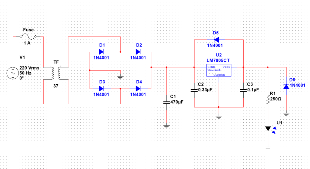
One thing to remember is the key role of a schematic is the visual representation of a circuit. Since there are so many tools to help us draw these schematics. That is why schematics may look different in terms of colors and representation, but they will always convey the same circuit.
2. Complete circuit
A circuit is considered complete if there is no open connection. Everything is connected perfectly. There is no wire coming off the circuit. There is no loose soldering connection and no sign of a bad connection.
For any circuit to work properly it must be complete. So pay close attention to connections when you are making your circuits. Pay close attention to circuit schematics and connect components exactly as given in the schematics.
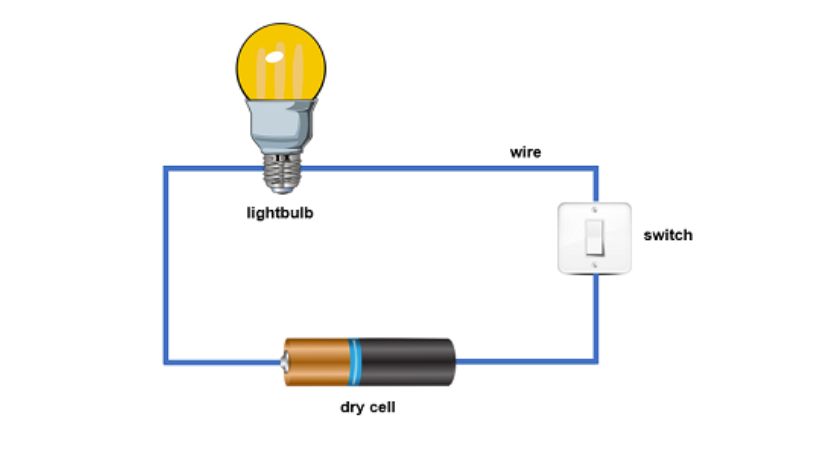
Look at the above simple circuit, you will see that there is no open connection so when the switch is no the circuit will work properly and it will light up the bulb.
What will happen if you accidentally make an open connection, i.e., you did not make the correct connection?
Well, foremost, the circuit or the part of the circuit will not work. If it works the results will be unreliable, and you feel that there is something wrong with the circuit. The third is you will add a lot of noise to your circuit.
3. Circuit node
Every electronic component is connected to make a circuit. The point at which these components join together is called the node.
You can consider the circuit node as a meeting point of any two components, as shown in the below diagram.
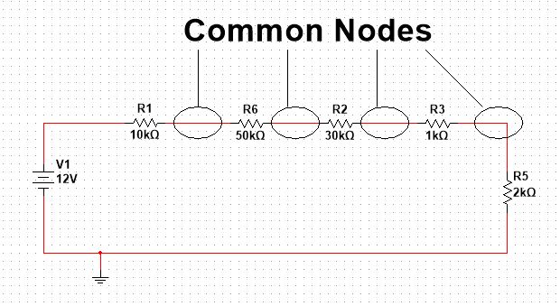
But remember the common joining point can be between two components, and it can be among more than two. Like I want you to consider a node as the meeting point of any possible connection in general.
4. Ground node (reference node)
In an electronic circuit, we measure voltages, current, and power to a common node. This common node is called the reference node.
But when the reference node is the negative of a power supply, i.e., it has the voltage value of zero. We call such a node the ground node as shown in the below diagram.
In the above diagram, the lower node is the ground node as you can see it is attached to the negative terminal of the voltage source.
If you pay close attention, you will see a special symbol at the ground node, i.e. the three lines. We use this symbol to represent the ground node.
5. Circuit branch
This is a really simple concept. Anything between the two nodes is called the circuit branch. For example, there are two nodes in the circuit the component in between these nodes is the circuit branch.
Don’t worry too much about this. These things are useful from an academic point of view but in real time any circuit element or component is the branch of the circuit.
For your better understanding, let’s an example.
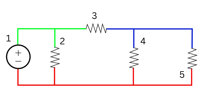
In the above circuit, there are 5 branches, one voltage source, and four resistors.
6. Circuit elements
Anything you use and see on a circuit board is called circuit elements. In simple language, circuit elements are the electronic components we use in making the circuit.
For example, the following are the fundamental circuit elements:
- Resistor
- Capacitor
- Inductor
- Transistors
- Diodes
- LEDs
Now the interesting to note here is these circuit components or elements come in both through hole and surface mount technology. Any circuit board has a combination of these two, i.e., a circuit may have through-hole elements as well as SMDs.
In summary, circuit elements are just the other name for electronic components. It is just this simple.
7. Loop and mesh
Any close path in your circuit is called the loop. For example, you take a node and make a path from that node and back to that node. You make a close loop.
Mesh is also a kind of loop, but it is special. It has no inner loops. This means a loop can have inner loops. But a mesh has no inner loop.
8. Open circuit
A circuit is considered open when it is incomplete. A circuit must make a complete loop, else the circuit would be an open circuit or incomplete circuit.
In simple language, an incomplete circuit is called an open circuit. Or more technically speaking any two electrical points or nodes on a board or circuit that offer infinite electrical resistance, we call it an open circuit.
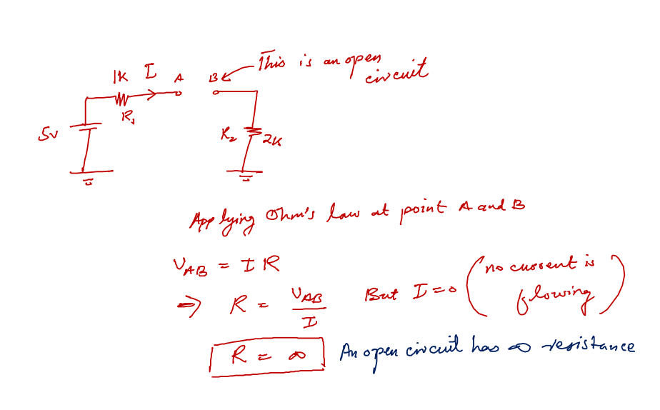
By applying Ohm’s law we can see, that any circuit points that offer very large (infinite) resistance will be treated as open circuit points. The interesting facts about open circuits are:
- There can be any voltage value across the points i.e. for example in the above picture point A and B have any value voltage.
- No current flows through the open circuit whatsoever.
In very simple words for beginners, when we cut a connection between any two components we make an open connection there. Consider two wires that you joined together. When you unjoin them you are just making them open circuit.
9. Short circuit
Opposite the open circuit, there is a short circuit. Technically speaking, any two electrical points on a board or circuit that offer zero resistance are referred to as a short circuit.
A short circuit is an unintended connection in a circuit, that allows a high amount of current to flow in the connection which can damage the components.
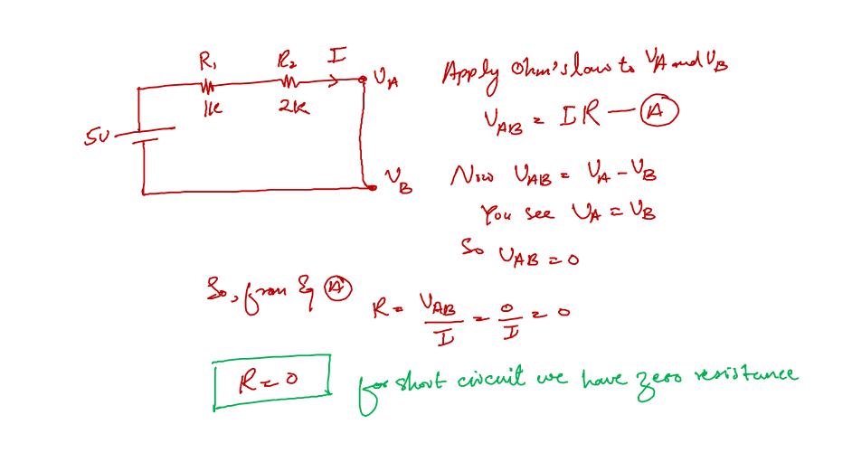
When we apply Ohm’s law to the short circuit we end up with zero resistance. The following are basic things you should keep in mind about a short circuit.
- The voltage difference across a short circuit is always zero
- Any amount of current can flow into a short circuit. And this is the reason we often hear a building catch fire because of an electrical short circuit.
Now we combine two components by shorting their terminal to one another, this is good and this is how we connect components. But if we short the connection of the two terminals of the same device we might end up damaging that device.
10. Series circuit
Any electronic components, no matter what size, are connected in such a way that the same current flows through each of them. This arrangement is called the series circuit.
In a series circuit the same amount of current flows in every circuit element. The voltage drops may be different depending on their resistance values, but the current value will always be the same.
Following is the example of a series of connected resistors:
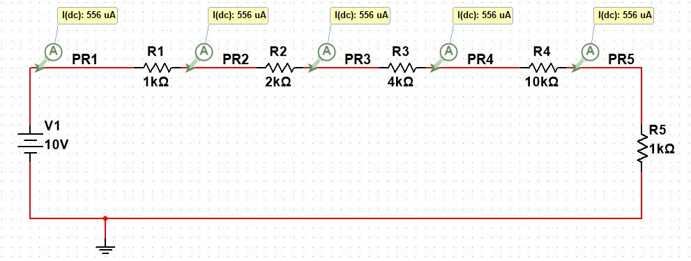
In the above simulation circuit, you can see the same current is flowing through each resistor no matter what is their resistance values.
11. Parallel circuit
This is like a counter similar to a series circuit. In the series current was the same. In parallel voltages are the same.
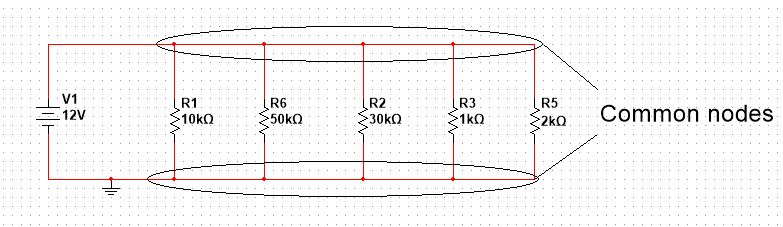
Any circuit components, no matter what size, are connected in such a way that each component has the same voltage across it. This arrangement is called the parallel circuit.
Following is the example of a parallel circuit in general and an example of parallel connected resistors:
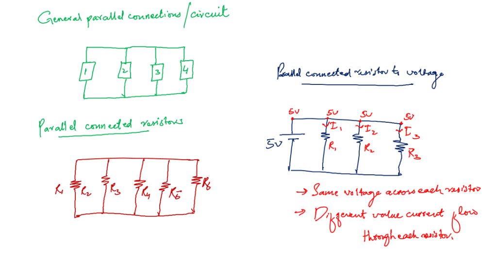
In parallel connected resistors (Parallel resistance) there are different paths for electric current to flow. The amount of current flow depends on the values of resistors.
12. PCB
You know, circuit prototypes help us to verify the results and give us a clear vision of whether the circuit is going to work in real-time situations or not.
When we are satisfied with the prototype results. It’s time to make a PCB for the circuit. PCB is short for printed circuit boards. These are the green boards you see in almost every product these days.
Following is the example of a PCB board:
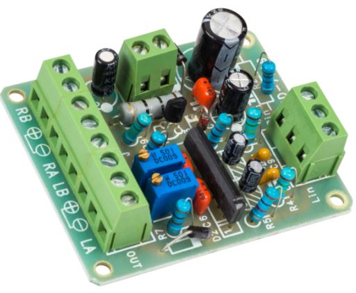
As we discussed, there are different software for circuit schematics. Similarly, there are PCB design software as well. We design the PCB in that software, generate the required files, and send them to PCB manufacturers for batch production.
13. Active components
When working with electronic circuits you will also hear the term active components.
Active components in electronic circuits are crucial elements that possess the ability to control and amplify electrical signals. These components can amplify a signal and produce power gain.
These components actively engage in signal processing and modification, which supports the operation of several electronic devices.
Transistors, diodes, voltage sources, and generators are some examples of active components.
14. Passive components
The passive components are fundamental building blocks in electronic circuits that do not require an external power source to operate. They shape and control the flow of electrical signals.
The passive components only receive the energy, which they can either dissipate, absorb, or store in an electric field or a magnetic field.
Among the primary passive components are resistors, capacitors, and inductors.
15. Load
You will also hear about the term load when learning electronic circuits. A “load” refers to any device or component within a circuit that consumes electrical energy.
It is the point in the circuit where the energy provided by the power source is transformed into a different form, such as light, motion, sound, or any other desired output.
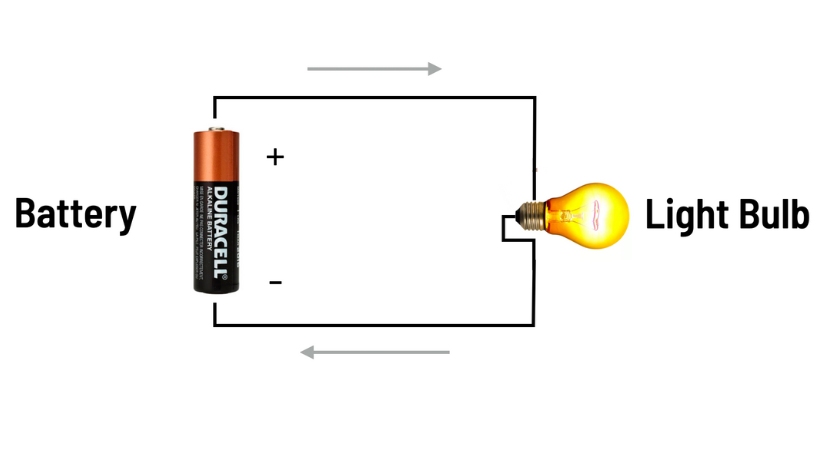
Considering the above circuit, the lightbulb is the load when the circuit is closed, and electric current flows from the power source (like a battery or the electrical grid), it encounters the resistance of the filament in the light bulb.
As a result, the lightbulb lights up and converts electrical energy into light energy. Without the load, the electronic circuit is of no use.
Conclusion
Electronic circuits are the core part of every electronic product that we use daily. These circuits come in green boards if you ever opened any electronic device.
An electronic circuit is a specific combination of various electronic components well connected.
Now if someone wants to learn about electronic circuits. I think it would be great because the number of electronic products is increasing, and we need more people to design amazing circuits for these products.
It is now a good time to become an expert electronic circuit designer. And just so know, this article is intended for someone who is just getting started.
Just like you are starting with a new field there are a few basic terms that you need to know. The same goes for circuits as well. There are a few fundamental electronic circuit terms that one must understand.
These are the following:
- Circuit schematics
- Complete circuit
- Circuit node
- Ground node (reference node)
- Circuit elements
- Loop and mesh
- Circuit branch
- Open circuit
- Short circuit
- Series circuit
- Parallel circuit
- PCB
Well, this article is all about these basic circuit terms.
So that is it. That is all I have for you about circuit terms and their concepts. I hope you enjoyed the article.
Thank you and have a grateful life.
Other useful posts: