

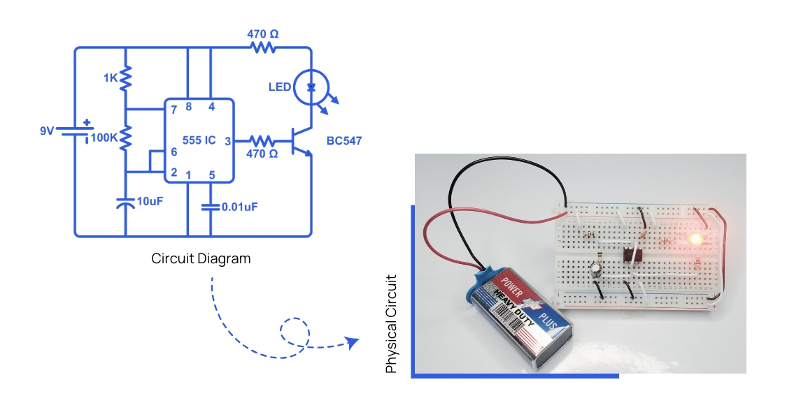
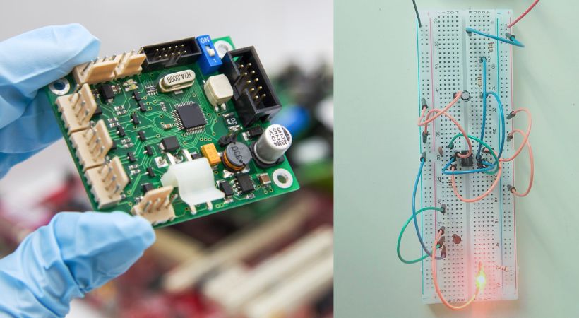
When you’re just starting with electronics, everything might look a bit overwhelming. Here’s a quick example: below, you see a circuit diagram for a simple blinking LED, and next to it is what that looks like in real life.
Right now, you might not recognize the components, understand the symbols, or know where to start.
That’s perfectly okay!
In fact, feeling this way is part of learning. Soon, you’ll understand how each part fits together, and you’ll be able to take any circuit diagram and turn it into a working project. That’s what it means to get started with electronics: building circuits, making mistakes, and learning every step of the way.
Before anything else, let me address the most common issue with beginners: the misleading myths.
Myths
People often think that electronics is a difficult subject to understand. In reality, it’s not.
It is a fascinating subject to get started with; all you need is the right mindset.
- The right mindset is that all you have to do is show the attitude that yes, I definitely want to learn it.
Following is some advice for you:
- Don’t rush the learning process.
- You don’t need to have an extraordinary magical mind to understand electronics.
- It is not like you will learn electronics in a day or week. So, you need to be persistent and enjoy learning each electronic concept.
- You don’t need to be very good at mathematics.
With that said, let’s learn electronics.
Electronics learning loop
There are millions of ways to start learning electronics. Because of this, a beginner gets confused. With experience, I have found a learning loop that best suits a beginner. It’s not perfect, but it’s easy and straightforward.
It has three main components:
- We start making electronic circuits
- We learn the required basics of electronics related to our circuits
- We make mistakes and learn how to correct them
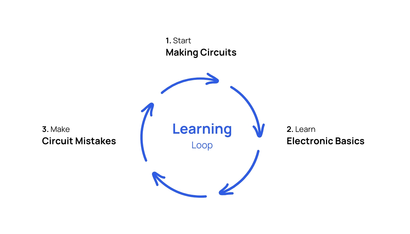
The loop continues. You make mistakes, and you learn from them. This strengthens your basics and makes you a skilled person over time.
This loop is based on the principle: The best way to learn electronics is actually by doing electronics.
Getting Started with Electronics
I believe that electronics can be best learned by actually doing it. Studies show that almost, more than 53% of people learn electronics better when they are involved in hands on practices.
See how my book will teach you electronic basics without having any prior experience
I, and we throughout the Yaman Electronics website, follow the latter strategy, learn electronics by doing.
Keeping this in mind, I came up with five simple steps that will help a beginner learn electronics basics and be able to make circuits on breadboard.
- Introduction to electronics
- Electronics component basics
- Electronics measurements
- Circuit prototyping (making) on breadboard
- Mistakes troubleshooting
Step 1: Introduction to electronics
In this step, we start with the definition of electronics. Because understanding the definition is very crucial.
Definition
Pay close attention to the word Electronics. You can see that it is similar to the word electrons – a subatomic particle.
This similarity is because in electronics we study the flow and behavior of electrons through semiconductor devices. This is the simple definition of electronics.
I feel to fully understand the above definition, a beginner should know the following main terms:
- Atom: Everything you see around you is a matter. Every matter is made of very small basic building blocks called atoms.
- Sub-atomic particles: The atom itself is made of tiny particles called subatomic particles. They are three, i.e., electrons, protons, and neutrons. Electrons have a negative charge, a proton has a positive charge, and a neutron has no charge.
- Semiconductor: Those types of materials in which the flow of electrons is not easy, but they can flow through them. For example, Silicon (Si) and Germanium (Ge).
I guess the definition of electronics is now clear. You may now apply this definition in your real world.
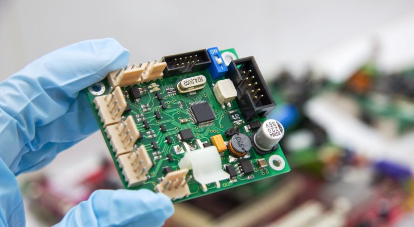
Open any electronic device, and you will see green boards. Carefully see the board and try to look at the different black components on the board. You will find out that those components will be made of Silicon semiconductor materials.
Electronic Sub Fields
It is important to know about the different fields and applications of electronics so we have a clear vision. And we can start with what we find interesting at the very beginning before wasting our time wandering here and there.
You know, electronics is a very vast field.
When you open your TV, you see electronics boards. You open a TV remote, you see electronics
You go to space and open a satellite, there you see electronics.
Not only that, but when you come back to earth and open your car there you see electronics, even when you open a medical device you see electronics.
I can go on and on, but I guess you got my point.
Electronics are everywhere and are being applied in all different fields. So let’s see some exciting branches and sub-fields of electronics.
I strongly suggest you spend some time studying and exploring the below fields before you make any firm decision.
1- Analog Electronics
This type of electronics deals with continuous real time phenomena. Like your voice is continuous in nature, to record and work with your voice we need to have a strong understanding of analog electronics.
2- Digital Electronics
Your laptop and mobile phone are all digital devices. To know how they work and how to design these devices yourself, you need to have a strong knowledge of digital electronics concepts.
3- Robotics
We need robots in every assembling and manufacturing industry.

So to know how those big robotics arms in car manufacturing factories work and how you can design them yourself, you need to start studying robotics.
4- Communication
You talk to your loved one all the time using your phone. This was not possible in the past.
In my time, I have to use pigeons to send out my love letter to my beloved.
But now you can connect to anyone with one click of a button. All this becomes possible because of RF communication electronics.
5- Industrial Electronics
The electronics in your child’s toy are completely different from the electronics that are responsible for the control of a whole industry.
In industry, we deal with electronics that can bear the high voltages and can do all the heavy-duty work for us.
To become an expert in those electronics, you need to have a solid knowledge of industry specific electronics.
6- Embedded Electronics & microcontrollers
This type of electronics is my personal favorite.
You take different types of electronic circuits, microcontrollers, Arduino, Rasbari Pie, and other boards. You combine all those and code them according to your requirements.
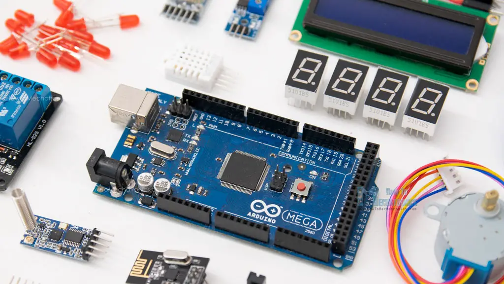
And then it does what you’re told and programs it to do so. This type of electronics technology comes under the umbrella of Embedded Electronics. Most of the embedded projects contain microcontroller boards and computer programming.
7- Power Electronics
Some electronic devices are low-powered. But in reality, we need to have electronic devices that can work with high voltages and power levels.
To handle high power and provide you with better results and efficiency, we often require you to work with power electronics concepts and terminologies.
8- Instrumentation Electronics
You know, you may see a digital weight measuring device. This is an electronic device that we use for measuring purposes.
Similarly, in the real world, there are a lot of things we want to measure ranging from home to industrial applications and quantities.
If you want to be an instrumentation engineer, then you need to have a strong knowledge of Instrumentation Electronics.
Above are some exciting and future promising fields. Let’s talk about fundamental terms we use all the time in electronics.
Fundamental Terms of Electronics
Basic terms are like the ABC of electronics. Like without ABC, you can’t make a word or a sentence in English.
Similarly, without basic electronic terms, you cannot understand concepts in electronics.
Please try to learn these basic terms with full dedication, as they will lay the foundation for your future success in the electronics profession.
It is not good and efficient for me to start talking about every term here. I will you a list of some of these terms. And you can learn them from any book (or on this website) of your choice.
- Electric Charge and electricity
- What is Current (Ampere, A) and Voltage (Volts, V)
- Product of Voltage & Current – the concept of Power (Watt, W)
- Relation of Voltage & Current – The Ohm’s Law
- Resistance
- AC & DC
- What are circuits, series and parallel circuits, open and short circuits
- KCL and KVL
The above are in my opinion, important to understand concepts. Of course, there are more than this, but I don’t want to scare you.
Spend some time learning these electronic terminologies and when you think you have learned them well, then move on to the next milestone or step, i.e., know about various electronic components.
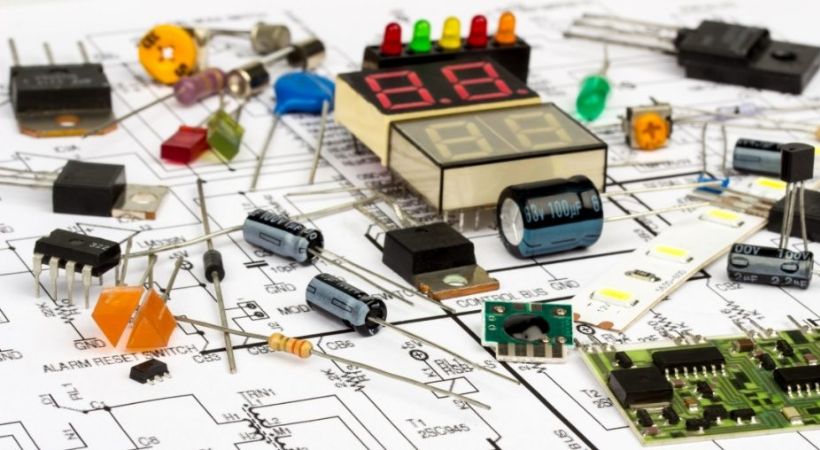
Step 2: Electronic Components
Electronic components simply mean those components or devices that we use to make electronic circuits.
You can surely imagine them as the building blocks of any electronic circuit, device, or system. No circuits can be made without properly connecting components.
All electronic components are made of semiconductor materials, i.e., mostly Silicon (Si) and Germanium (Ge).
Electronics is the study of the flow and behavior of electrons through semiconductor materials, and these electronic components are made of semiconductors. That is why they are called electronic components.
Following are basic electronics components to understand if you want to get your hands dirty with basic electronics circuits as fast as possible.
As you continue your journey in electronics, you will encounter much more complicated electronics components as well.
Step 3: Learn about measurements & tools
We talked about the basic terms and components above. The next step for learning electronics is to utilize those basic terms and electronic components and make some projects.
Let me tell you, projects and circuits are fun to design and make. But to make a physical circuit, you need to have tools.
You have heard me talking about currents, voltages, and resistance.
The big question is how you can measure them. For an electronic circuit to work properly, we need to provide it with the proper voltage and current levels.
And how we get to know these proper voltages and current levels. The answer is simple, by using electronic measuring tools.
Following are some fundamental tools a beginner should have before getting started with electronics.
- Multimeter
- Oscilloscope
A multimeter is the fundamental device. While oscilloscope is optional at the very beginning stage.
Keeping this in mind, let’s learn more about the multimeter and see what it is and why we need it.
Multimeter
You can say that a multimeter is a device we use to measure the following:
- Voltages and current
- Resistance of a resistor
- The capacitance of a capacitor
- Circuit continuity
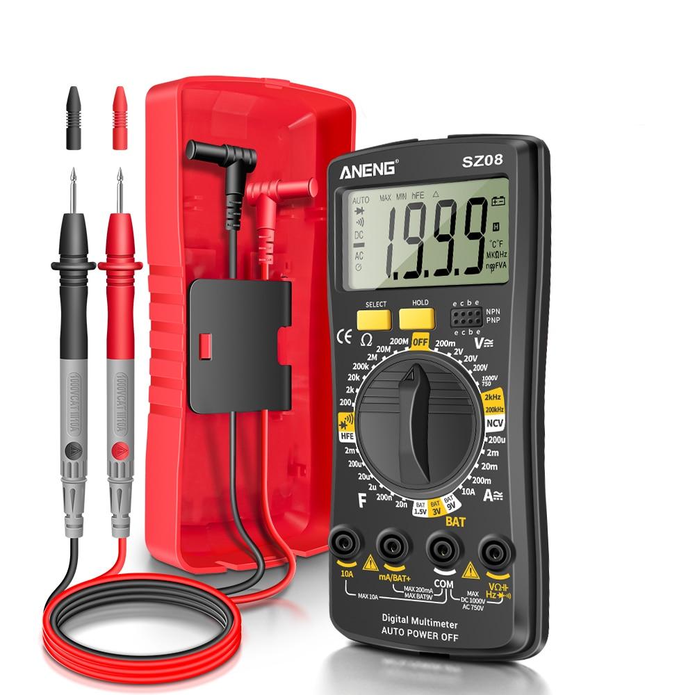
It has a screen for reading, a round dail (function switch) to choose different measurement modes and probe leads.
For a beginner, it is good to learn how to use a multimeter. For this, I have written a detailed post. If you are interested, you can read it here (Multimeter basics).
Step 4: Making Circuit Prototypes
We talked about the electronics terms and components. Also, we talked about how to measure and test components. Now what we need to do is to start doing experiments. And believe me, joining these electronic components together is fun.
When you properly connect components, we end up with useful and working electronic circuits. Circuits are nothing but the proper combination of various electronic components.
Electronic circuits are one of the core parts of any device these days.
Your computer has electronic circuits, your keyboard has electronic circuits, your mouse has electronic circuits, your mobile has electronic components, your TV has electronic circuits, and your alarm clock has electronic circuits.
I am just looking at my room right now and telling you all about the circuits. Let me go outside and see other examples as well.
Alright!
Right now, the airplane flying over my home has electronic circuits. I think you got the point now.
There are two types of circuits I want you to remember:
- PCB Circuits
- Breadboard circuits
PCB stands for Printed Circuit Boards: they are circuits with components soldered on them. While breadboard circuits are the circuits with no soldering. We can test our circuits on the breadboard. Such testing circuits are also called circuit prototypes.
A prototype of a circuit is: making a real-time circuit on a breadboard from a circuit diagram. Prototyping a circuit is a great way for beginners to make actual circuits on breadboard and test them.
Following is the circuit prototype of the LED Flashing Circuit:
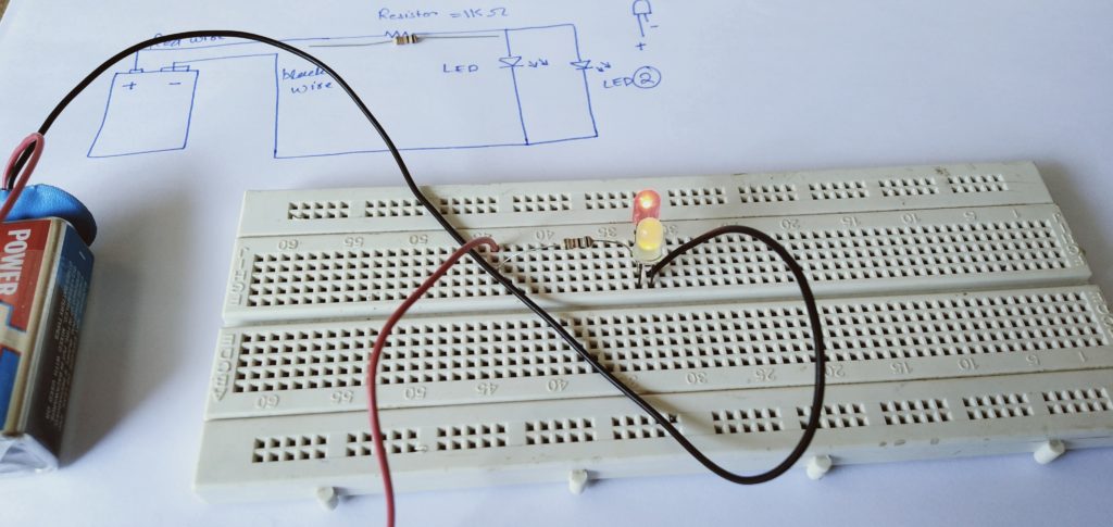
On the top we have a circuit diagram, in the middle, we have a physical representation of the same circuit diagram on a breadboard called the circuit prototype.
Circuit schematics help us make the physical circuit easily and correctly. It is like the map of a building.
The circuit diagram can be simple and can be complex depending on the project.
Ok. So when it comes to electronic circuits, there are a few basic concepts that you must know before working and designing any of your circuits. There are a few and are the following.
- Circuit Schematic
- Open Circuit
- Short Circuit
- Parallel Circuit
- Series Circuit
The above terms related to circuits are used all the time. So please spare a decent amount of time studying these concepts.
Following are the tools that we need to prototype.
- Breadboard
- Jumper wires
- Power supply
- Multimeter
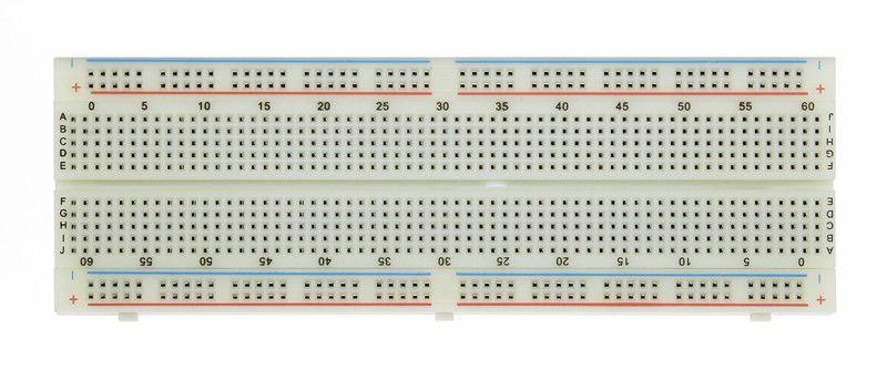
1. Breadboard
For circuit prototyping, a breadboard is the main tool. We put together all the components and jumper wires in a breadboard.
It is a tool that helps us make our circuits by holding all the components and connections together. It helps us transform a circuit diagram into a physical circuit.
Following is a breadboard:
Breadboards are very easy to use. We can use the same breadboard for as many circuits as we want. If we make a mistake, we can easily undo it, correct it, or change it.
2. Jumper Wires
These are the wires we use to make connections between various components and a power source. In general, we use jumper wires for connecting two points on a circuit.
Following are examples of jumper wires:
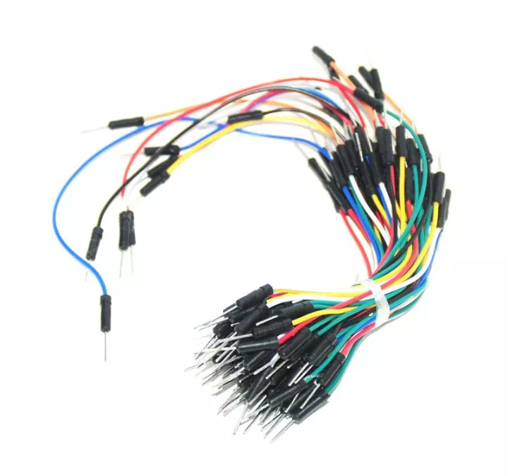
Jumper wires come in different shapes and sizes. You can choose any type as long as they are working fine.
3. Power Supply
To power your prototype circuit, we need a power supply. You can have a stand alone power supply. Also, you can use the breadboard power module as well if you are just getting started with electronics.
Following is a breadboard power module:
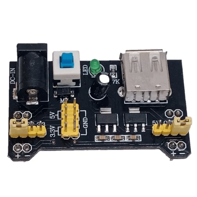
At the beginning, 5V -12V is what you require. So if you want to go for a solo power supply, make sure it is safe and has an adjustable voltage option.
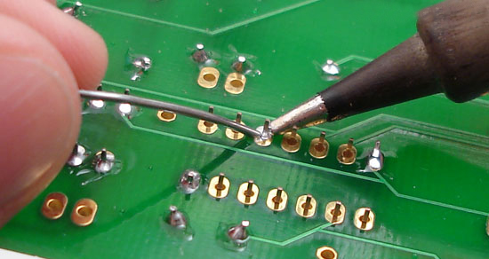
Soldering
After successful testing of circuit prototypes on breadboard. You can convert it into a PCB board.
For this, you will required to learn how to solder. This reliable process of joining various electronic components on PCB is called soldering.
You don’t need to always do soldering on PCB. Sometimes we also do soldering on Veroboards as well. It depends on what project we are working on.
We also do soldering for circuit repair work as well. So, do not generalize soldering to just the PCB board. Remember it as, the process of joining various electronic components and devices together in the most effective way possible.
Step 5: Troubleshooting (Correcting Mistakes)
Making a circuit or projects on a breadboard can be tricky for beginners. They may make some mistakes due to which the circuit may not work.
How to handle those mistakes?
Well, we analyze and handle those mistakes by careful circuit troubleshooting.
Electronics circuit troubleshooting is a process using which we rectify the problems in the circuit prototype and correct them.
Usually following are the mistakes one can make on a breadboard.
- Loose connection
- Short connections
- Loose components
- Faulty components
- Circuit schematic misinterpreting
Apart from these mistakes, sometimes we overlook the very basics. For example, voltage reverse connection and discharged battery usage.
Your First Project — LED Circuit
We covered the 5 steps to get started with electronics. Let’s put them into action and make your first circuit, the LED circuit.
LED circuit is the first circuit people make when they start learning electronics. This was my first circuit too. And I still remember blowing my LED. This circuit is simple, but it is a great way to step into real electronics.
Following is the circuit diagram of an LED circuit:
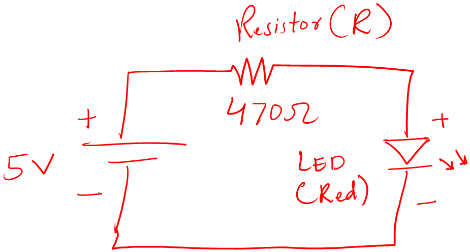
You can see it has a voltage source, a resistor, and an LED. The resistor and LED are in a series connection. It means the same amount of current is flowing in the circuit.
We use a resistor in front of the LED. The reason is to limit the current flow to the LED. This limiting current ensures that the LED will not burn out and will be safe for long use.
Alright! Let’s prototype.
Take a breadboard, jumper wires, LED, 470 Ohm resistor, power module, and multimeter.
1. Measure the value of components
Here we have a resistor, we need to measure its value before putting it in a breadboard. To do that, follow the following steps
- Take your multimeter
- Set it to resistor measurement (by moving the center dial to the Ohm sign)
- Connect the black probe of the multimeter to the COM port, and the red probe to the Ohm port.
- Connects the probes of the multimeter to the legs of the resistor
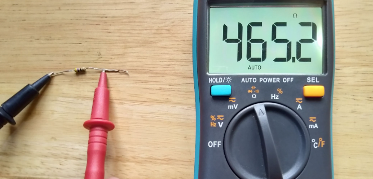
- See the results on the multimeter screen
- That is how we measure the resistance of a resistor.
Make sure the multimeter shows it’s a 470 Ohm resistor. In actual readings, it may not be idle but the readings may be close to it.
In the case of an LED circuit, we have one resistor to measure. But other circuits will have other components, you will all measure them.
2. Putting components in the breadboard
In this step, put all the components in a breadboard. Try to make the circuit clean and place components according to the circuit diagram.
Following is the example of an LED circuit:
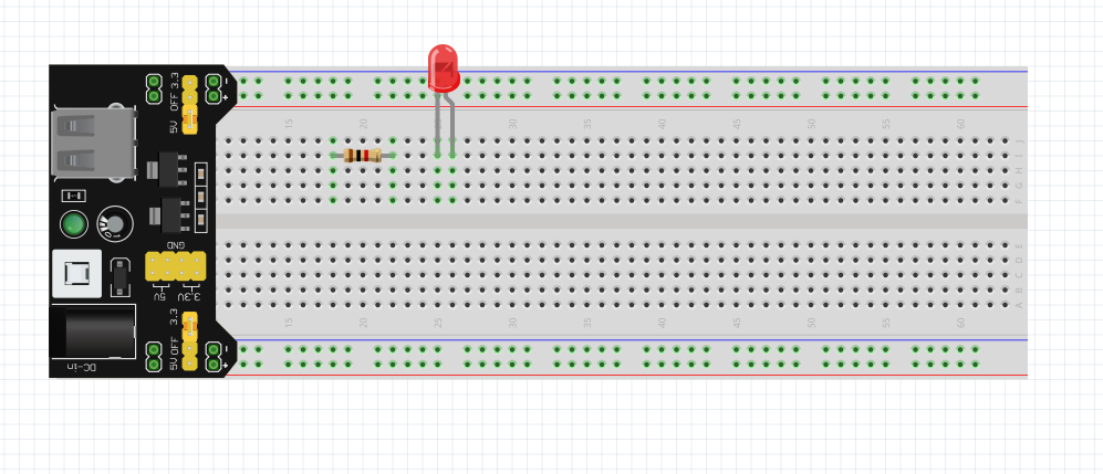
I put resistor before LED. Because in the circuit diagram it was before LED. Please don’t place components too far away from each other. Don’t use long and extra wires. Try to make the circuit as neat and clean as possible.
3. Making the connections
Now, using jumper wires, make the connections according to the circuit diagram. This part may be tricky when you work with a complex circuit. So pay very close attention.
Because a wrong connection will lead to a bad circuit.
Following is the example of an LED circuit:
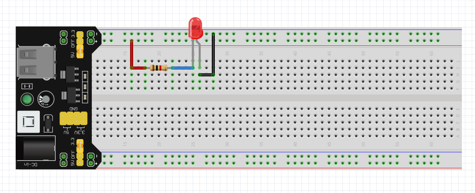
You see that everything is connected as per as circuit diagram. One leg of the resistor is connected to the + of the LED and the other is connected to the + of the power supply.
It is good to follow the convention when making connections:
- Use red jumper wire for + connections
- Use black for – connections and ground
4. Power the circuit and test
After making the connection, it is time to power the circuit and see if it works as it is supposed to.
Always power the circuit when you check the circuit 2 times and ensure there is no connection error or any other error.
Because in case there is a short connection in the circuit, powering up may damage the component.
From Project Idea to Final Manufacturing
The above roadmap was to get you started. But I want you to know, it doesn’t stop there. The whole idea of electronics is to make useful products for mankind.
Also, when you have some working experience with electronics. At some time, you will take on some projects of your own.
So what the journey would look like, and what would be the steps you take to bring your idea to the world?
Idea & Validation
The first thing is, that you have an amazing idea for a product or project. You sit down to think about everything and do all your market research.
Market research is really important.
Because at the end of the day, I don’t want you to create a product that no one likes or even wants to have.
That product would be a great learning experience for you but in the real world as a real electronics designer, you have just wasted your resources and a lot of energy.
So with that being said. You got a product idea. You have done all your market research. It is time to mass manufacture it and share it with the world.
Let’s see an overview of how you are going to do so.
Circuit Design
After idea validation, you will start circuit designing.
Circuit design will be the most significant task in the whole project.
Your goal for the circuit design should be to make an optimal and commercial product-level circuit.
By commercial, I mean the circuit parts should be easily available, and the circuit cast should not exceed the market you want to hit.
Because at the end of the day, you want to have a low price circuit that the majority of people can buy.
By low price circuit, I don’t mean to reduce the quality of the circuit. By low price I mean you need to design an optimal circuit, there is just no other way.
For the circuit design, you will be using a lot of brainstorming.
And of course, you will need good simulation software to test and verify your designs.
Prototyping
After you are done with the simulation and get an optimal circuit, it is time to prototype it.
Prototyping a circuit is a great way to verify the simulation results.
Once you make a prototype circuit and test it in a real-time situation – you are happy with the results. It is time to make a PCB for that circuit.
PCB stands for a printed circuit board. These are boards you can find in any electronic product.
To create a PCB, you need to have good PCB design software and good soldering skills.
Manufacturing
You are done with the PCB design. It is time to contact a manufacturer and make a sample of your PCB to check the results.
After you verify the sample and the results are what you’re looking for. It is time to bulk produce the product and sell it to the world.
Conclusion
Learning electronics is so simple and easy. It is just people have told us that electronics is hard.
But in reality, electronics is the most interesting and profitable subject you will ever learn in your life.
I call it profitable because you can see we are already in the digital age. And in the future, those people will have high-paying jobs and understand electronic technology well.
Artificial Intelligence is taking on the world. And you know what, it is only possible because of advancements in electronics.
So, if you have decided to get started with electronics. Then you have just made a wonderful decision in your life.
This article is all to help you see the whole picture of electronics. As I am assuming, people reading this article will be complete beginners. So I try my best not to use too much technical language.
This article is a simple roadmap for a student who wants to get started. It starts with the definition of electronics and ends with the final manufactured electronics product.
I hope that through this article I have added a little value to your life.
Thank you and have a good life.
Other useful posts:
Shokran Abbas for your nice blog
Welcome 🙂
Assalamualaikum Sir ,literally this blog made my route clear and best way to learn electronics is quite tough task,but you made it easier with your instructions and encouragement.Thank you so much for sharing this priceless knowledge.
Thank you 🙂
Yes i am a beginner but your wealth of experience make me feel encouraged and willing to study more.
Am studying how to repair circuit boards.
i will appreciate it if i can have your whatsapp number / email or twitter handle.
Tanks
Chris
Thank you 🙂
That’s what I was searching for.
Thanks a lot
Welcome 🙂