

Basic Electronics: Complete Beginner Roadmap (2026)
Hi,
You want to learn some basic electronics, but you don’t have a clue. Don’t worry, nobody has, especially me.
That being said, you are in good hands (not sure about this) to learn basic electronics.
What I learned living on this planet for 29 years is that every subject starts with a definition. You want to learn biology, you should first learn what biology is before anything else. Surprisingly, learning electronics starts with defining electronics as well.
By definition: Electronics is an engineering subject where we learn to design and build circuits that we use in various products and applications. That’s it.
Now, we know the goal of learning electronics is to make useful circuits. It is clear that we need to first understand what a circuit is, how these circuits are made, which components to use, and how to design and build circuits. Right?
And if you successfully answer all the above crazy questions, you just learned all the basics of electronics. Wow, I wish it could be that simple.
But, trust me, it is just that simple.
If I say this one article is what you need to master electronics, then it would be complete nonsense. Or, maybe I am just too genius, which I am definitely not.
My intention is to give you a complete picture of starting from defining electronics to your first working circuit. By the end of this introductory article, you’ll be able to make and understand the following flashing LED circuit from scratch – even if you don’t have a clue about electronics.
And also, my secret hidden intention is to inform you. I am a genius, and you should definitely buy my book, Make Your First Electronic Circuit. Of course, I brag about my book everywhere where I get a chance.
Alright,
So you got my intentions and the goal of this article. Now, let’s get started.
Definition of Electronics
In simple words,
We define electronics as the field of engineering in which we learn how to make useful electronic circuits
The circuit we make can be used in many applications. For example, we can make circuits for military, health devices, and artificial intelligence, or maybe we can make circuits for hobbies and fun as well.
The next question is, so what is an electronic circuit?
Electronic circuits
In simple words,
An electronic circuit is the carefully connected combination of circuit components and wires that perform a specific task
Let me explain;
If you open an electronic device like a TV remote, you will see a green board inside it. This green board is an electronic circuit. The task of the circuit is to switch the channels on TV while you sit.
The circuit in your mobile is doing the communication task. The circuit in your laptop is doing all the amazing jobs on your screen.
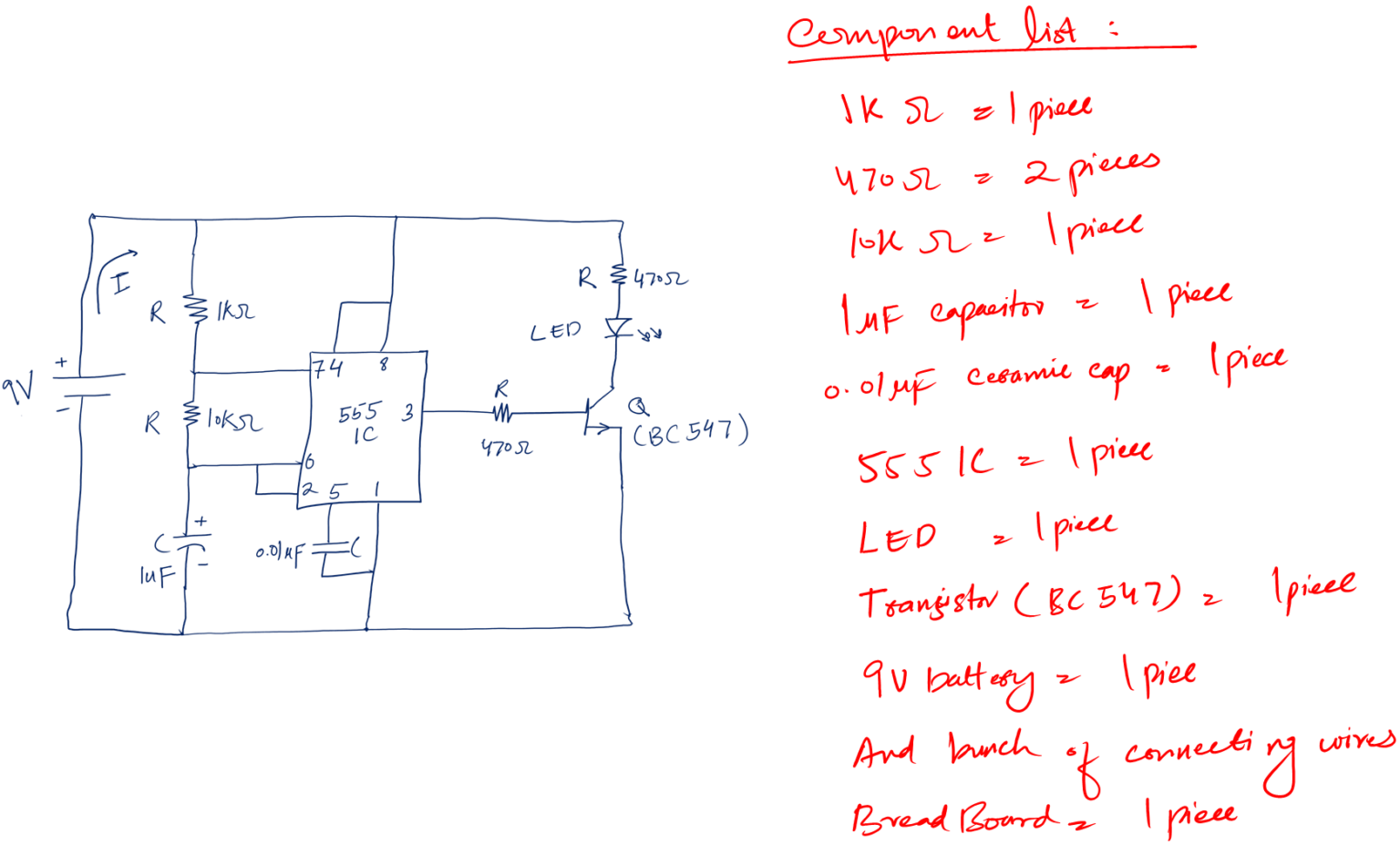
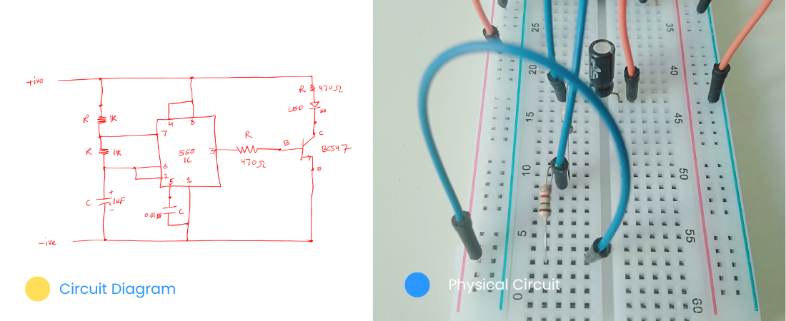
Similarly, below is the circuit diagram of the flashing LED circuit. The task of this circuit is to blink the LED on/off.
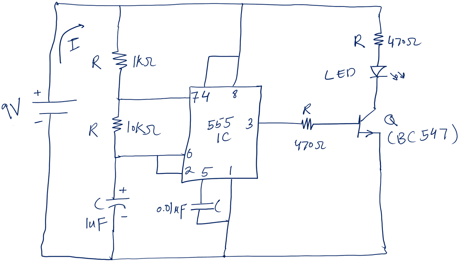
It is a cool-looking thing I am calling a circuit diagram; another name for a circuit diagram is a circuit schematic.
But what is a circuit diagram, you may ask?
a. Circuit diagram
In simple words,
A circuit diagram is the drawing of a circuit on paper that helps us make the actual circuit from it.
The circuit diagram can be simple and complex, depending on the project. Now, the observation you may have is: what are these different symbols and things in the circuit diagram?
Well, they are the circuit components.
b. Circuit components
In simple words,
As a building is made of bricks. Similarly, circuits are made from circuit components, also known as electronic components.
In a proper circuit diagram, we represent each circuit component with its unique circuit symbol.
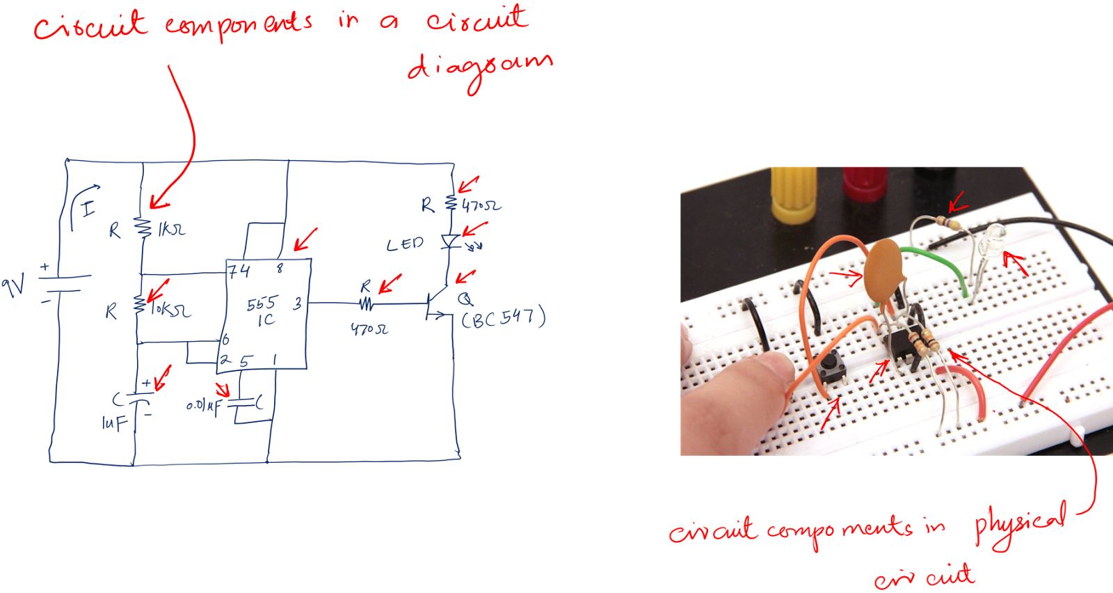
You see, we have different types of components. They are different in shape, size, and structure.
So a circuit is nothing but a proper and logical combination of various components connected together.
I believe that now you may feel that to make a working circuit, we need to understand these circuit components.
And you are right.
But, back to our building analogy. A building is made of bricks, but the core elements to hold these bricks are the cement and iron bars.
Cement and iron bars make the skeleton of the building. Similarly, cement and iron bars of any electronics project are the key electronics terms. Without these terms, it is impossible to build the building of electronics.
These terms are:
- Voltage
- Current
- Power
- Ohm’s Law
Let’s just understand these first, and then we will be back to our flashing circuit.
Basic electronic terms
Understanding and learning basic electronics terms is essential for a beginner to design and know how an electronic circuit works.
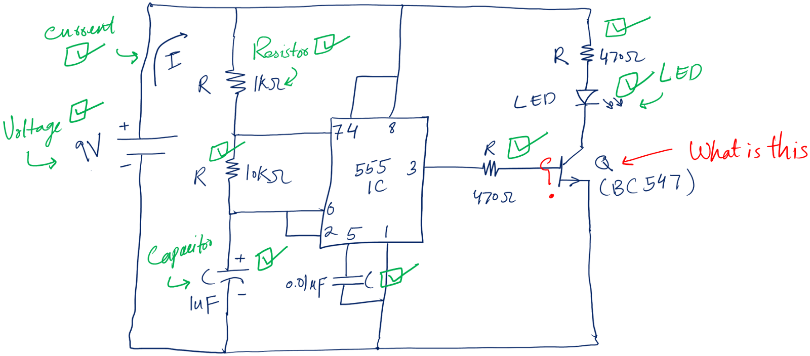
See the following diagram.
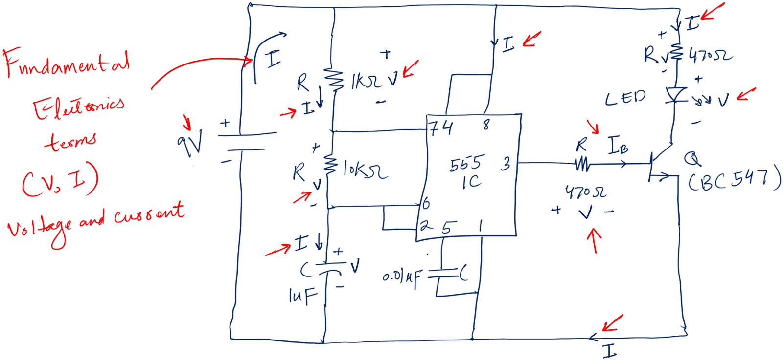
Whenever you see a circuit, you will see terms like (V, and I) in every circuit. You must wonder what these terms are.
Let’s understand these terms in detail.
1. Voltage
Just look at yourself. You need the energy to work properly. For energy, you use food.
Right?
Similarly, electronic circuits need energy as well. And voltage (V) is their energy source.
In simple words,
Basically, a voltage is the energy source that pushes the energy in the entire circuit.
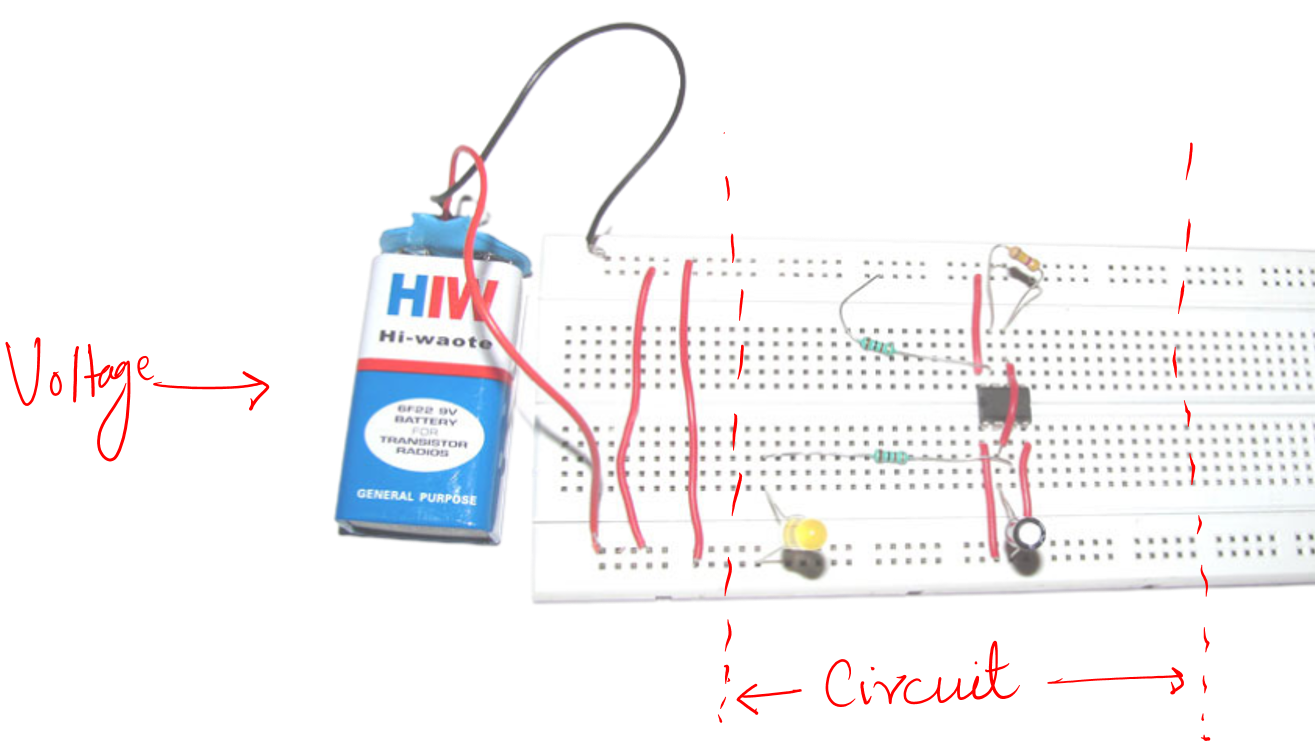
The above is a physical voltage source called the battery. The following is the symbol of the voltage source for the circuit diagram.
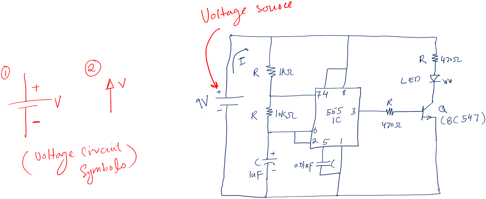
As you can see, in symbol 1 or the above battery. A voltage source has two terminals.
The terminal that pushes the energy is the positive (+). The other is the negative (-) terminal – here the remaining energy comes back to the voltage source.
As we eat food, its energy is divided among the different parts of our body. Each part gets energy depending on its requirements.
Energy travels from the positive terminal to every circuit component, where each component receives its energy and then returns to the negative terminal.
So the main voltage divides across different circuit components in an electronic circuit like food energy division in different parts of our body.
The last important thing about voltage is that we measure it in terms of Volts. In simple words, the unit of voltage is Volt (V).
2. Current
In simple words,
Current (I) is the amount of energy the voltage source pushes per unit of time.
To understand this in depth. Let’s use the following analogy, which we call the water analogy.
Consider the voltage source as a water pump, water as energy, and current as the flow of water.
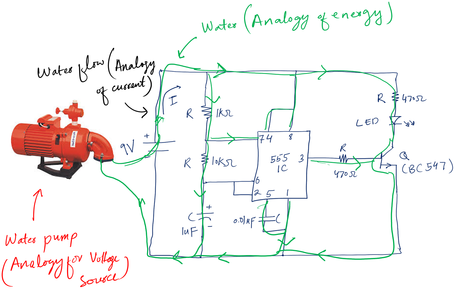
The water pump will push the water. The water will flow all over the circuit through pipes (connecting wires).
The same happens with the voltage source. It pushes the energy. This energy flows throughout the circuit and we call this energy flow per unit time the current.
The unit of current is Ampere (A). This means we measure current in terms of Ampere.
The voltage and current are related to each other and this relationship is given by Georg Simon Ohm. This relationship is called Ohm’s Law.
3. Power
In simple words,
The product of current and voltage is power. It provides a better understanding of how electronic circuits and components work.
Power can be defined as how much energy a circuit component consumes or is supplied with time.
For better understanding, let’s again consider the water analogy: the water pump is a voltage source, water is energy, the flow of water is current and power is the rate at which water does work, like turning a water wheel or turning on the light.
Power can be calculated by
P=V*I
Each electronic component can consume a specific amount of power without damaging itself; this is called the power rating. The power rating factor should be considered when designing any circuits.
4. Ohm’s Law
Ohm’s Law is a fundamental principle in electronic circuits that describes the relationship between voltage (V) and current (I).
When voltage is present in the circuit, the current will flow, so this means there is some relation between voltage and current, the presence of voltage makes the current flow.
Think about the water analogy. The bigger the water pump (voltage source), the higher the water flow (current).
From the above statement, we can say that voltage is directly related to current.
Following is a simple mathematical explanation of this law.
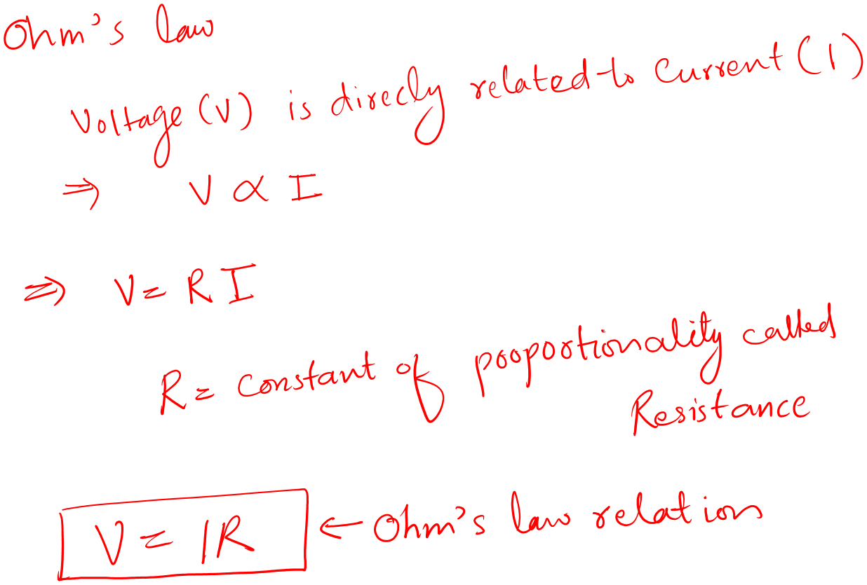
The “R” in Ohm’s law represents resistance; it’s the opposition to the flow of current. This resistance (R) is of great use. This value determines how much current should flow. The measuring unit of resistance is Ohm.
Every component we saw in the above circuit has its resistance. And that is why different amounts of current flow through them.
It means each component takes the energy according to its requirements in a circuit.
This also means that each component will have its voltage value across it according to the Ohm equation. We call this voltage value a voltage drop of a component.
In quick summary, voltage (V) is an energy source, current (I) is the flow of energy in the circuit, and Ohm’s law is the relation (V=IR) of these two.
Alright!
Up until now, you have understood the basic terms of electronics; it’s time to learn about various basic electronic components.
** Hey, if you want to build a billion dollar business in a day and an amazing body, then check out my book, Make Your First Electronic Circuit. One customer just got his dream life partner while sleeping. Such miracles are normal when you buy my book.
Basic components
Remember we were talking about circuit components? And got the feeling that to build a useful circuit, we need to understand circuit components.
Let’s explore the circuit components in our flashing circuit one by one. I have chosen this circuit because it has almost all the fundamental components.
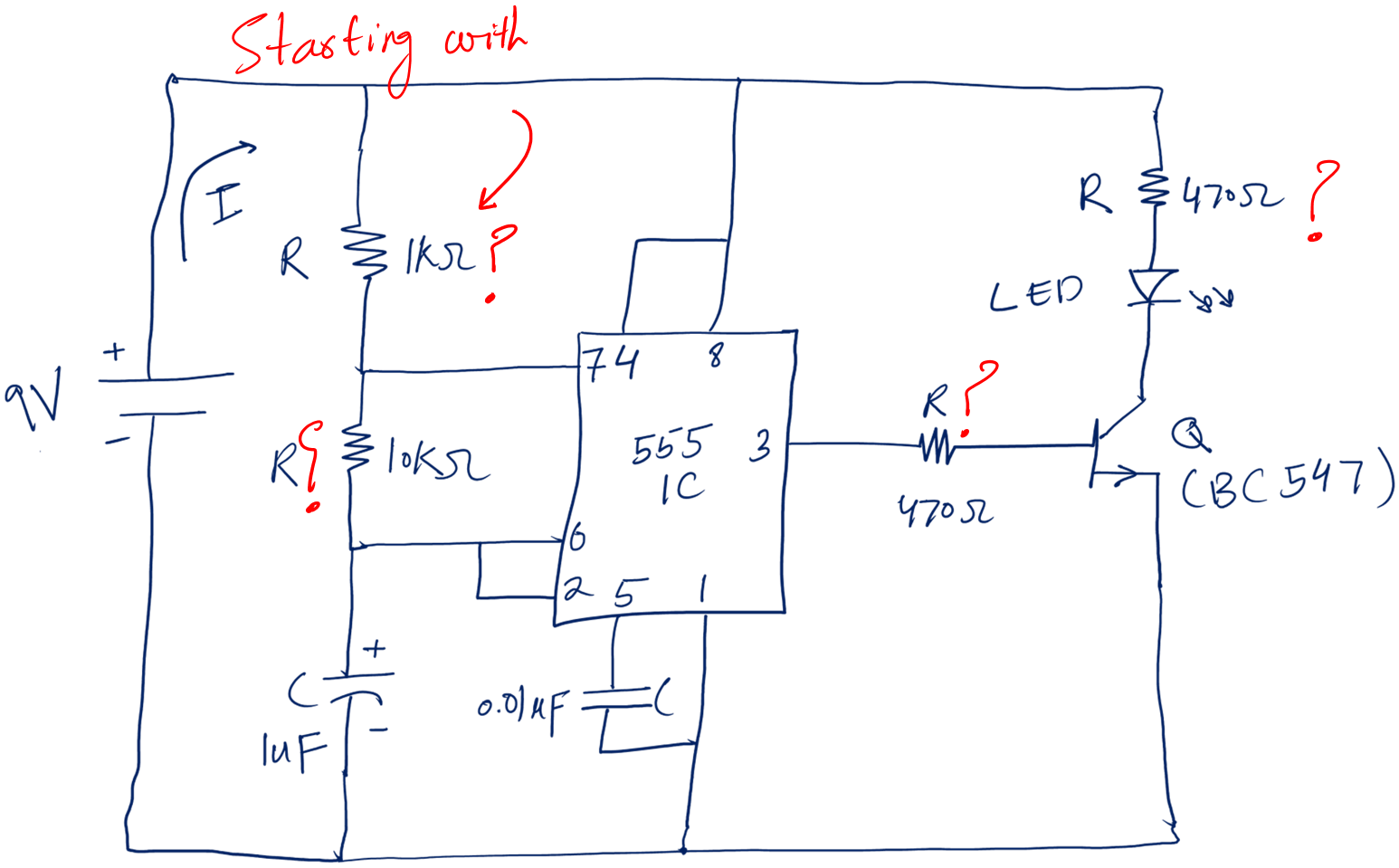
Starting with this zigzag element.
Can you guess what it is?
It is a resistor.
1. Resistor
In simple words,
A resistor is a component that has two terminals and is used to limit the current flow in a circuit.
You can also define it as, a component that provides opposition or resistance to the current flow in a complete circuit.
To study a component we are interested in:
- Its circuit symbol
- What it looks like physically
- Circuit functions – like what the component does in a circuit
Following is the circuit symbol for a resistor and examples of actual resistors.
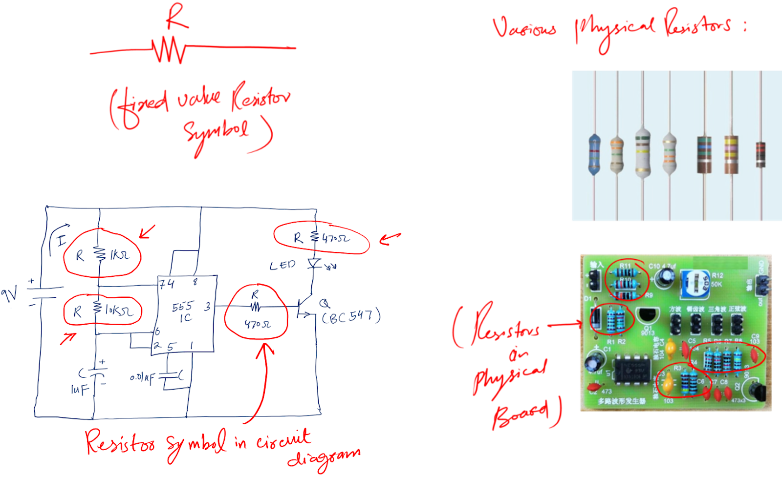
Circuit functions:
- A resistor is treated as a safety component, as it limits the current flow to our desired values.
- Besides current limiting, a resistor is also used as the voltage divider.
Moving on to our next component.
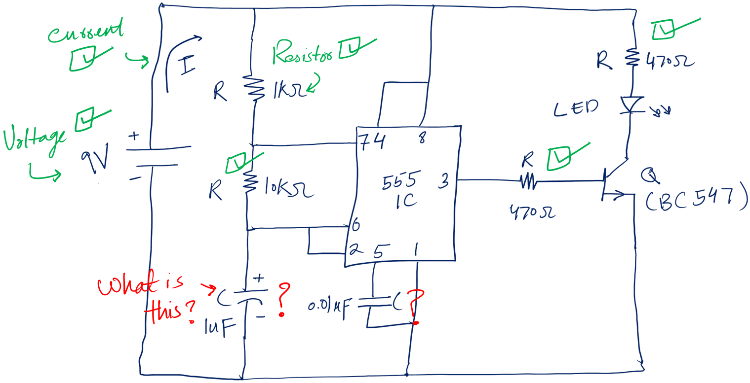
Can you guess the component with red question marks?
It is a capacitor.
2. Capacitor
In simple words,
A capacitor is a component that can store energy.
It is like an energy source that stores energy from the main voltage source and gives this energy back to the circuit when needed.
Following is the capacitor symbol:
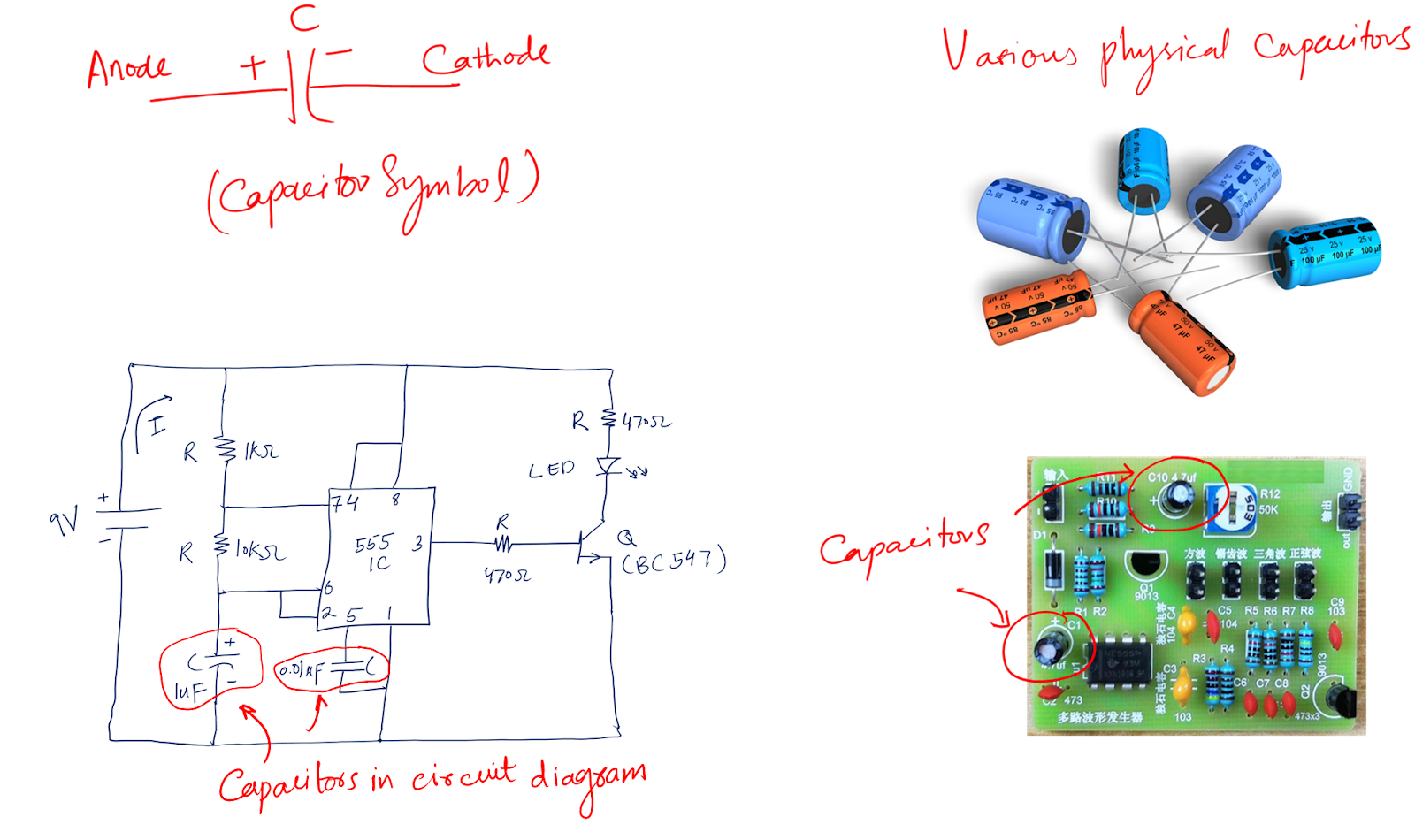
A capacitor is measured in terms of capacitance (C), the ability to store charges.
The unit of capacitance is Farad (F).
Besides the unit, there are two types of capacitors
- Ceramic capacitor
- Electrolytic capacitor
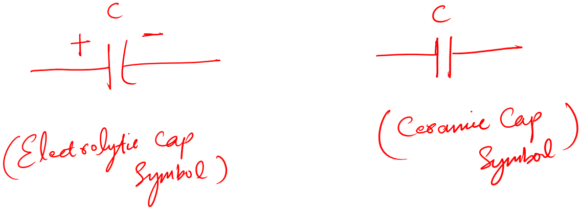
An electrolytic is polarity dependent (it has + and – terminals) capacitor while the ceramic is independent of any polarity.
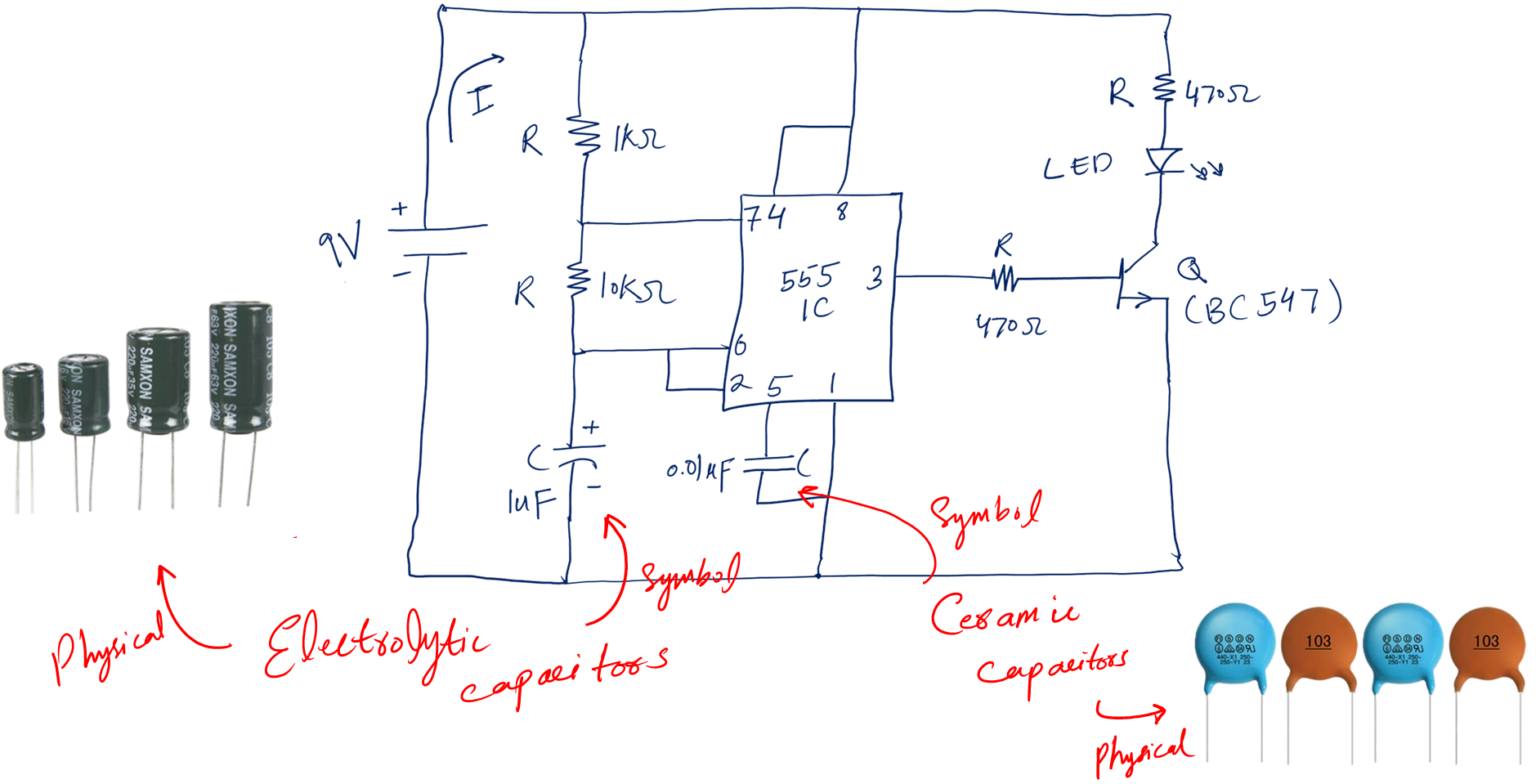
Circuit functions:
In the real world, we do not have any pure voltage to work with.
- To get close to the ideal pure voltages capacitors are used as a filter.
- If you open any electronic device, you may see some big capacitors close to the input power line.
- They are there to filter out the input impurities and noise before letting it to the rest of the device.
Moving on to our next component.
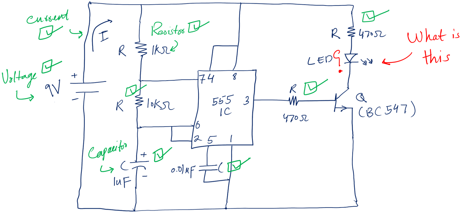
Can you tell the one with the red question marks?
It is called LED.
3. LED
In simple words,
LED stands for light-emitting diodes. These are the types of circuit components that upon application of voltage glow and emit light.
Most LEDs have two terminals, and they come in various shapes and colors.
One terminal is called the anode (+) and the other terminal is called the cathode (-).
Following is the circuit symbol of an LED.
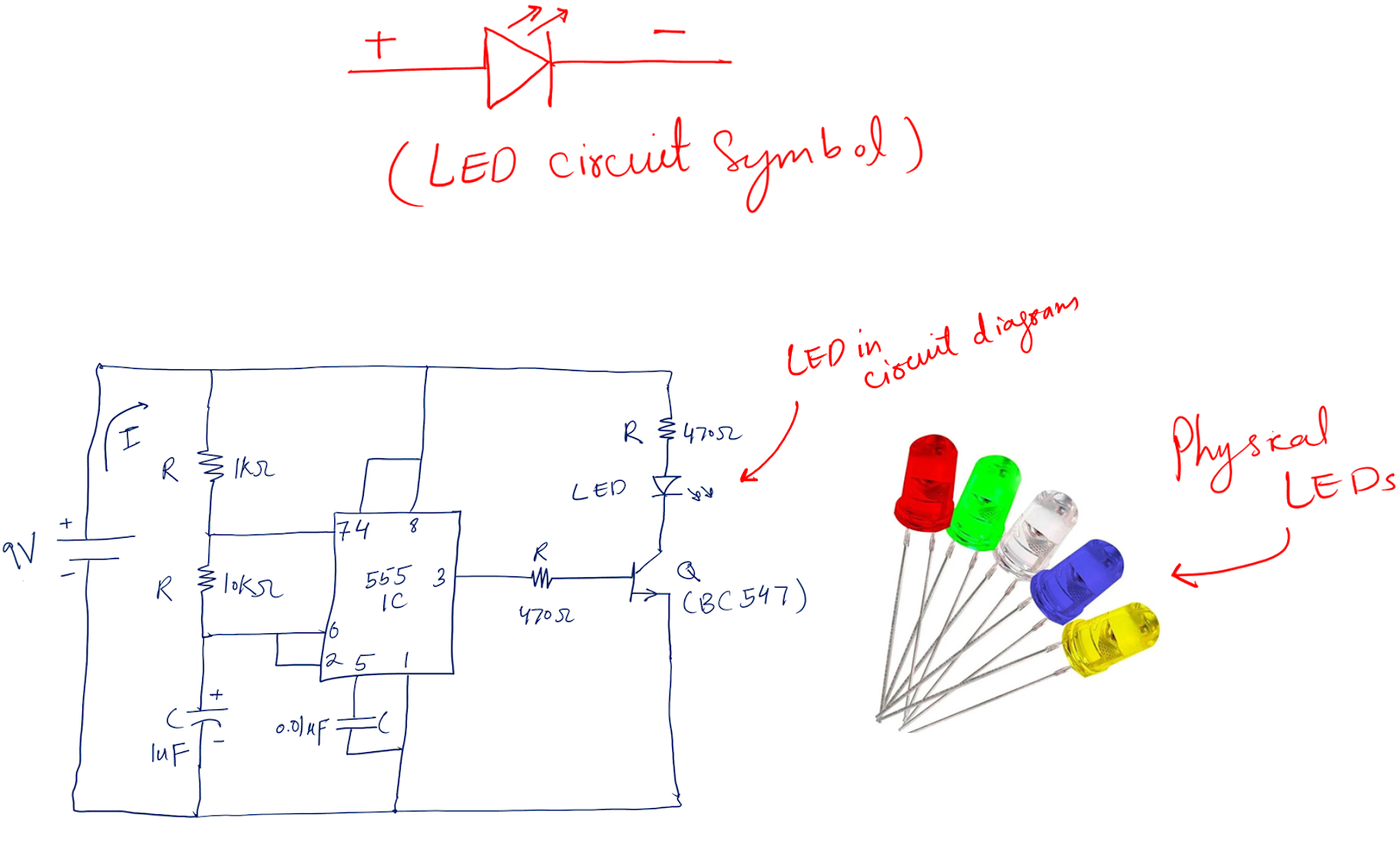
Circuit functions of LEDs
- The main function of an LED is an indication
- The best example is your laptop which maybe you are using now. See the power indicator light. It is an LED.
- Decoration purposes
Personally, I used to include many colors of LEDs in my beginner projects. They are amazing. The best part is, they are very inexpensive.
Alright so that is a little about LEDs. You can learn more about led bsics and why it is the important type of diodes (also a circuit component).
The next component is the transistor.
If you see the above circuit, you will be happy we have almost covered the whole circuit. Well done.
4. Transistor
If this component was not invented in Bell Labs, we would have no modern world. This advanced technological era is only possible because of a transistor.
A transistor is a three-terminal device that does the following:
- Amplifies current
- Switching
Following is the circuit symbol of a transistor.
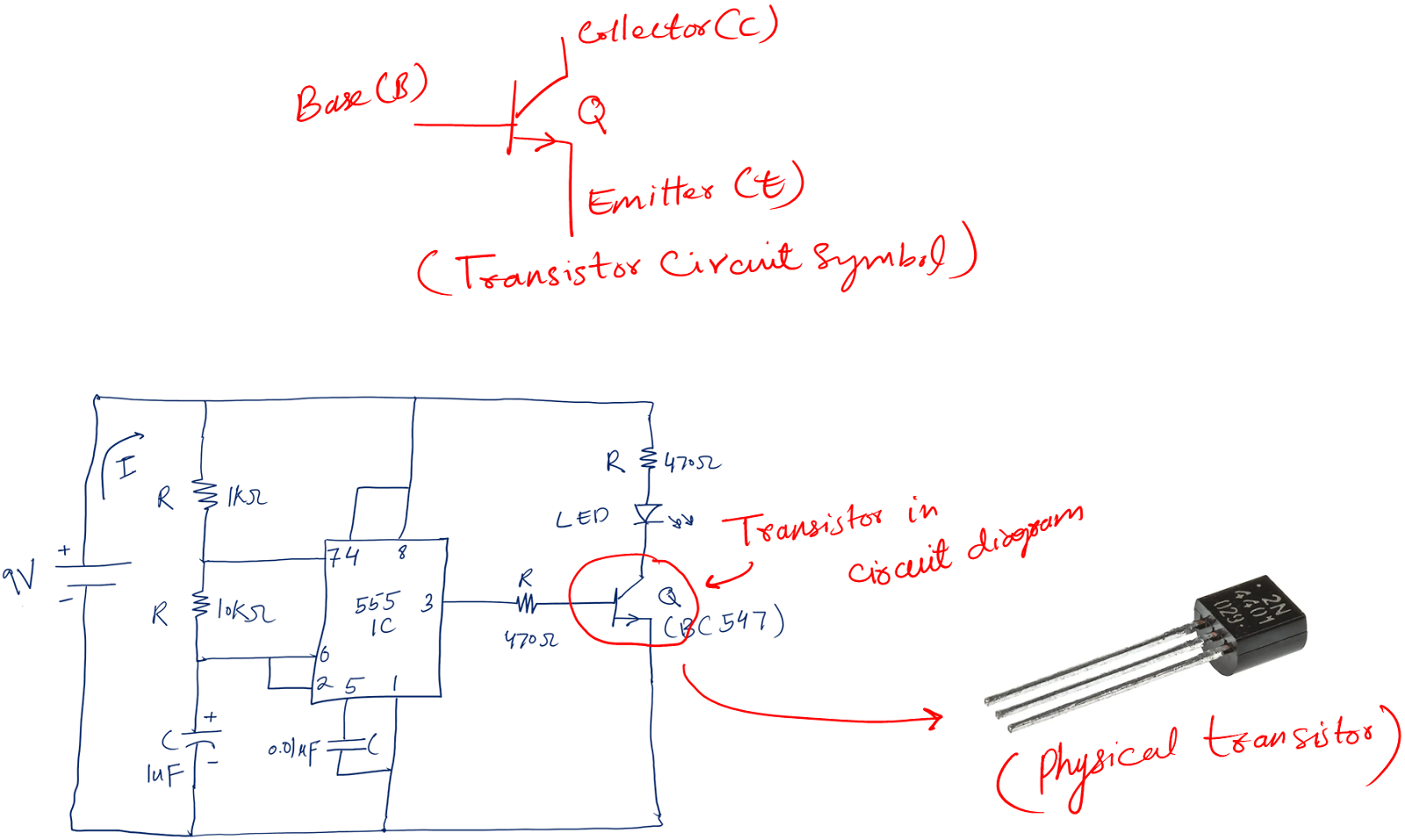
The three terminals are the base (B), collector (C), and emitter (E).
The question is why do we use it?
Let’s try to understand it by the following example (using the flashing LED circuit).
In the flashing circuit, the LED requires a 20mA current to glow. But the circuit at point A can give only 10mA.
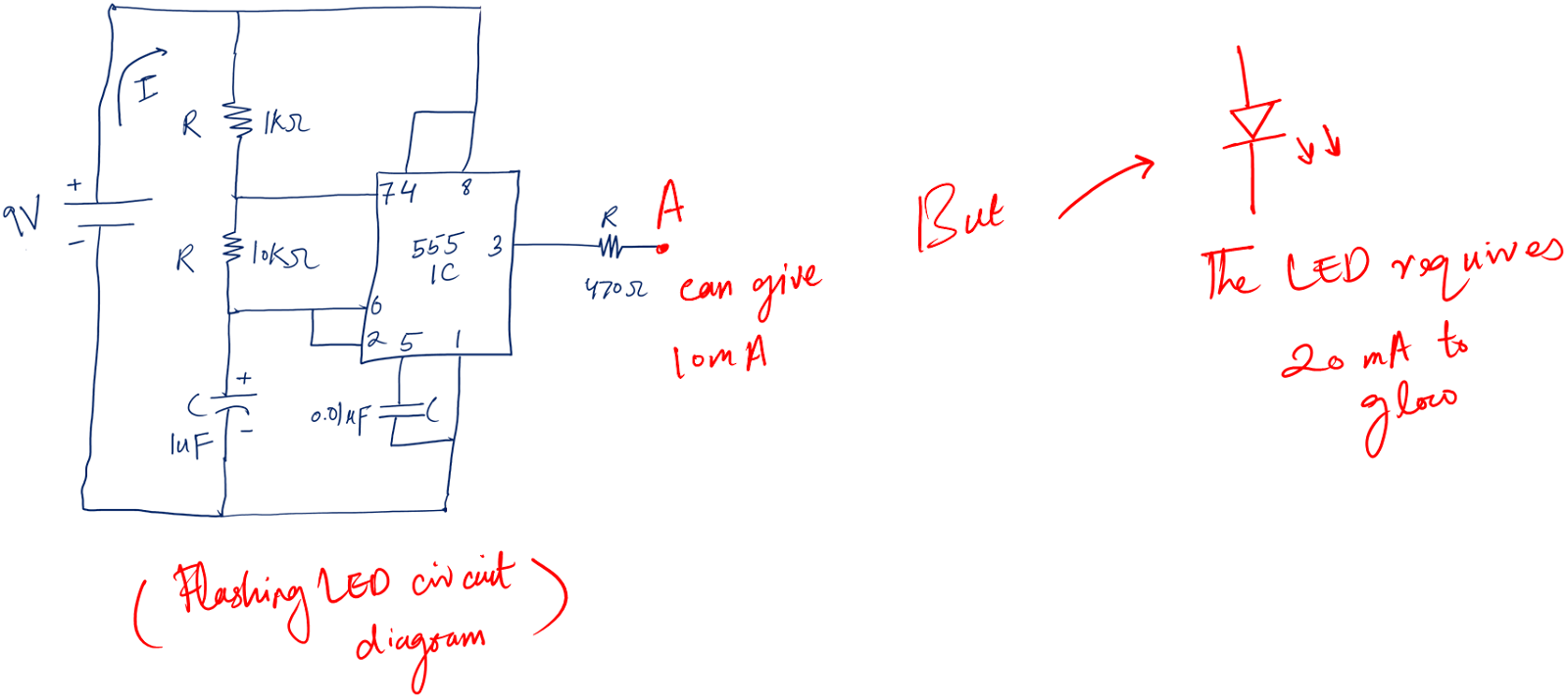
If we connect the LED directly to point A, the LEDs will not glow.
In such a situation, the transistor comes into action.
It takes the weak current (i.e., 10mA in the above case) and amplifies it to our required values (i.e., 20mA in the above case.)
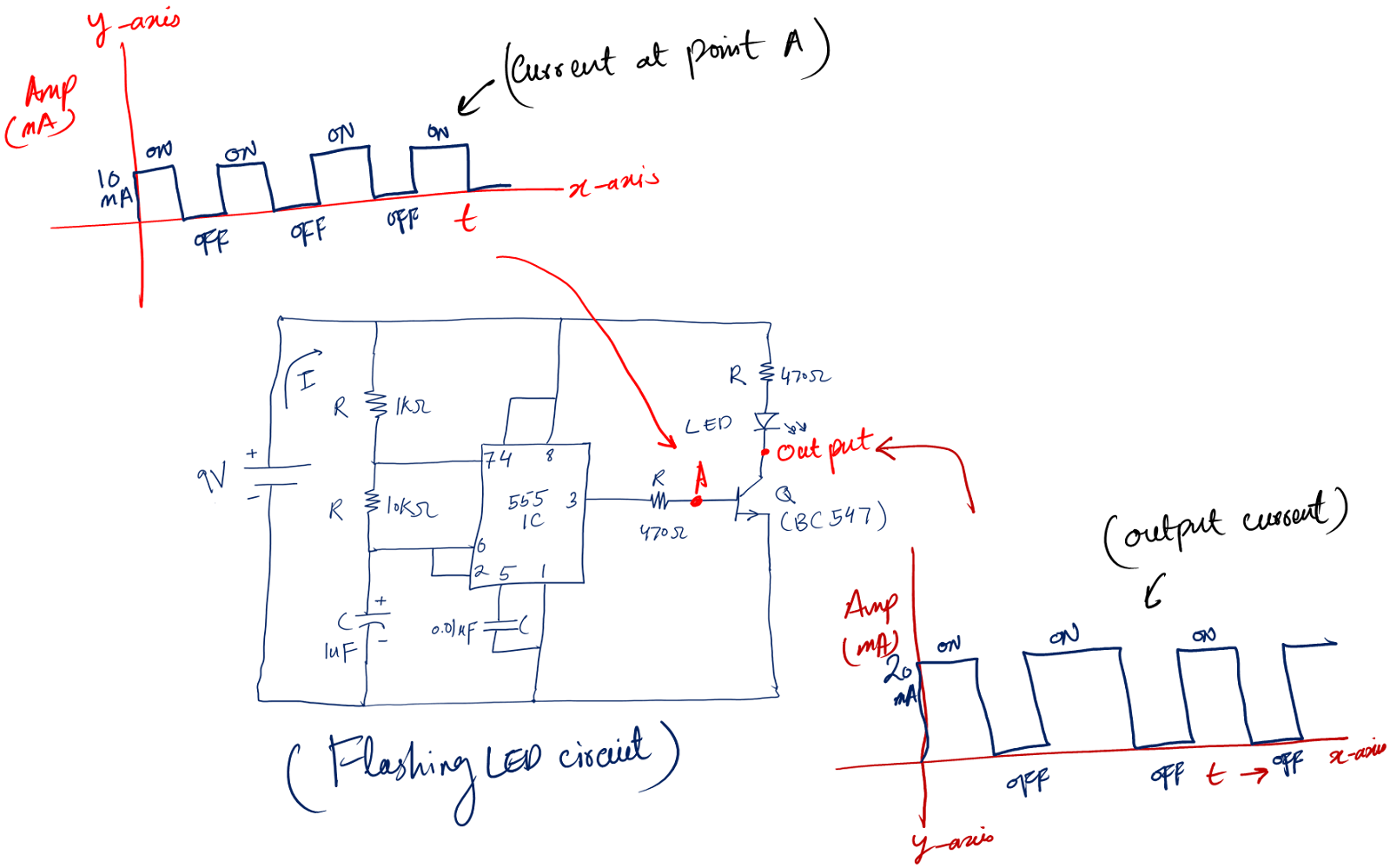
Above, we saw transistors as amplifiers.
But they also turn on the LED above for some time, then turn it off.
Similarly, the transistor turns the LED below on for some time, then turns it off – thus creating the flashing LEDs.
So, it is a switch as well.
I believe the journey of learning electronics basics for beginners is making some kind of sense to you now.
Moving to our last component in the flashing LED circuit.
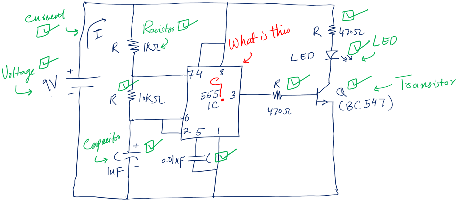
The pointed red is called the IC, short for an integrated circuit.
5. Integrated circuits (IC)
As the name suggests, it is a complete circuit integrated (made) on a Silicon chip. In simple words, it is a complete circuit that we make on a silicon chip.
IC can have various numbers of terminals. One IC may have 8 terminals (pins) while the other may have 18 pins. This number depends on the task of the IC.
Following is the circuit symbol of the 8-pin IC (the one used in our flashing circuit example).
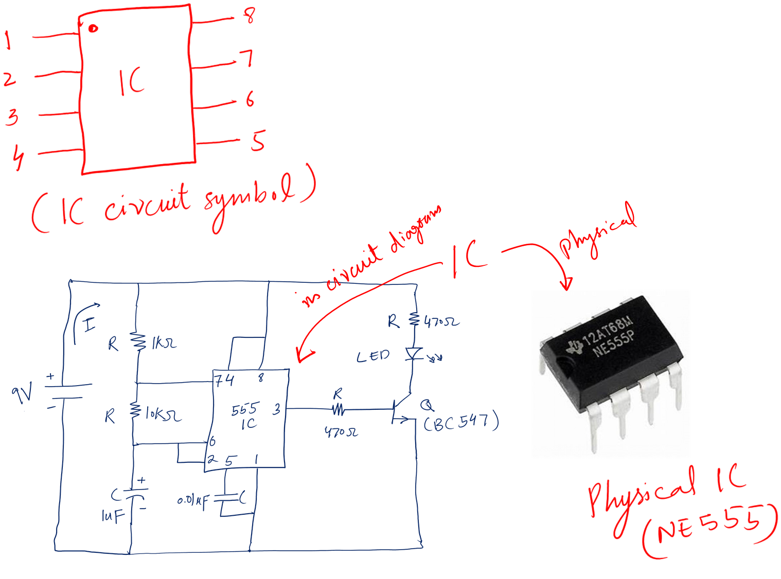
Circuit functions:
- You can say that the IC is actually the circuit inside some package. And you are right. That is what we want in electronics.
- We want small size, portable devices – and this is possible only by making ICs.
With this, we have covered all the components in the circuit. These are fundamental components I believe a beginner must master.
So, looking at our final circuit. We can now tell what it is, what it does, and what is the name and function of each component.

And by the way, the lines that are connecting all the components. These are the connecting wires.
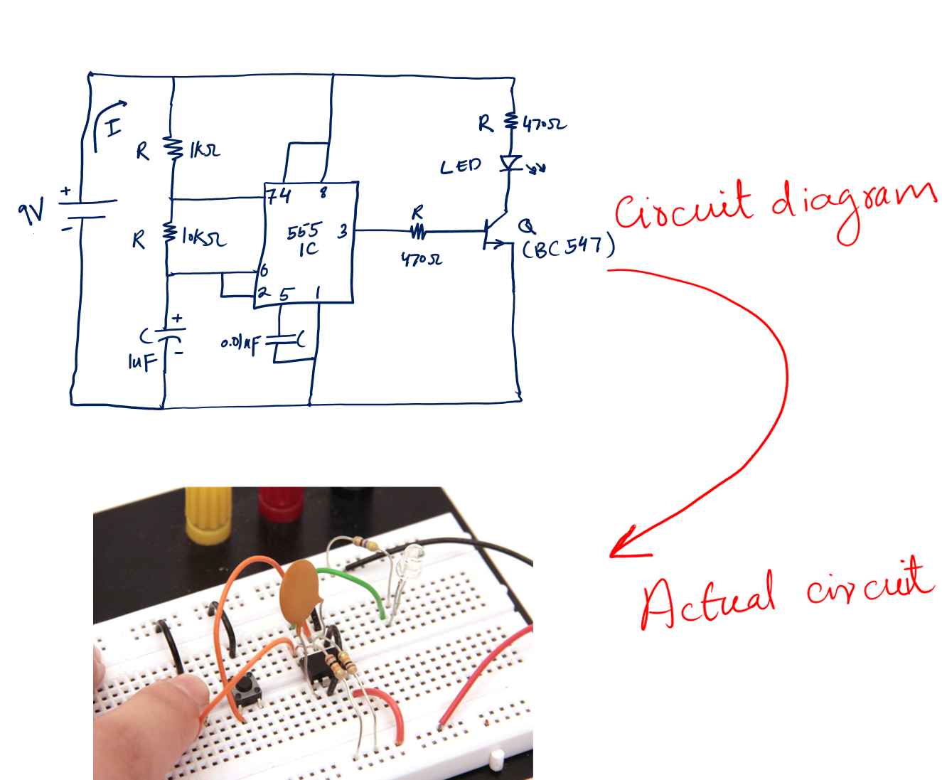
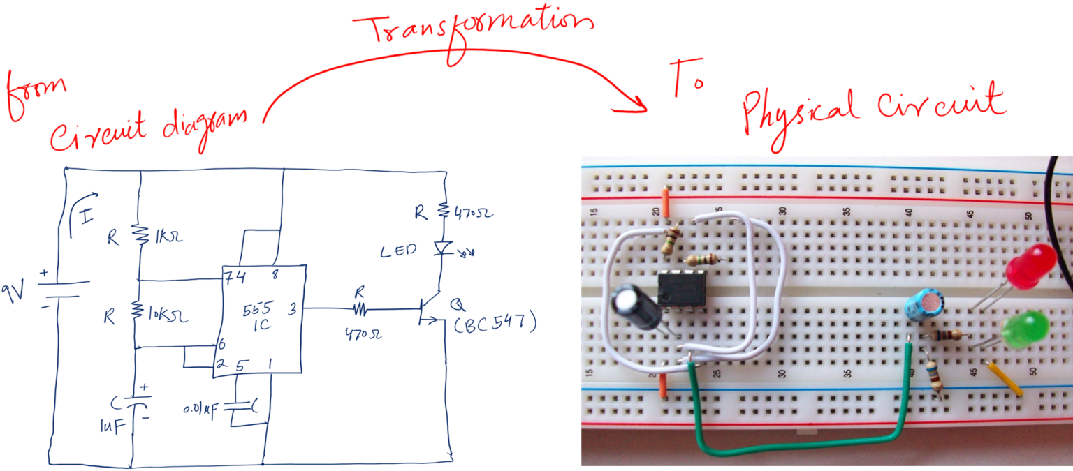
Now the next thing is to convert this circuit diagram into an actual physical circuit.
Sounds interesting?
To make this conversion, we need the following fundamental electronic tools.
Tools in electronics
In the above basic electronics sections, we covered some fundamental electronics components and terms.
Let’s talk about some awesome tools that we use almost all the time for our projects.
- Breadboard
- Multimeter
- Component tester
- Component kit
1. Breadboard
In simple words,
A breadboard is a tool in electronics used to make electronic circuits
By making a circuit, I mean putting together all the components according to the circuit schematic.
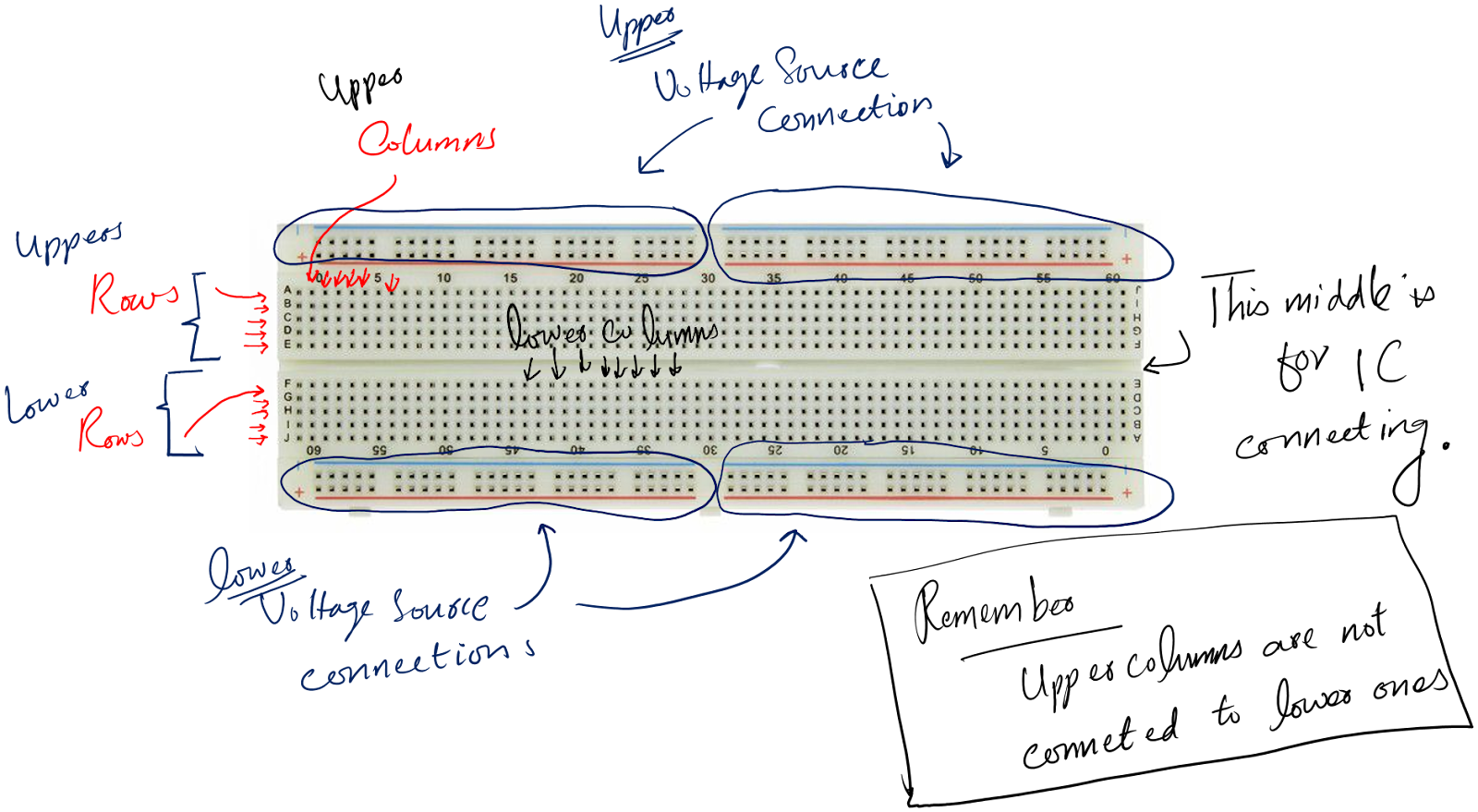
Following is the breadboard.
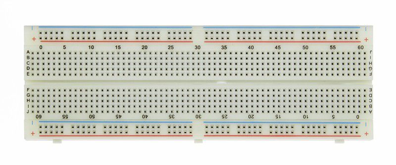
It has several rows and columns. Can you see the A, B, C … J? These are the rows. The dot in each row is not connected to the dot of the next row.
The numbers you see (0,5,10,15, …). These are columns. The dots in the same column are connected. The upper columns are not connected to the lower columns.
Breadboards are very easy to use. We can use the same breadboard for as many circuits as we want.
If we make a mistake, we can easily undo, correct, or change it.
Our breadboard version would be similar to the following for our flashing circuit.
It is clear that without a breadboard, we cannot effectively put and connect components to make our circuits.
2. Multimeter
Upon looking at our flashing circuit diagram. You will find out that next to each component there is some numeric value.
This numeric value represents the unit of that particular circuit element.
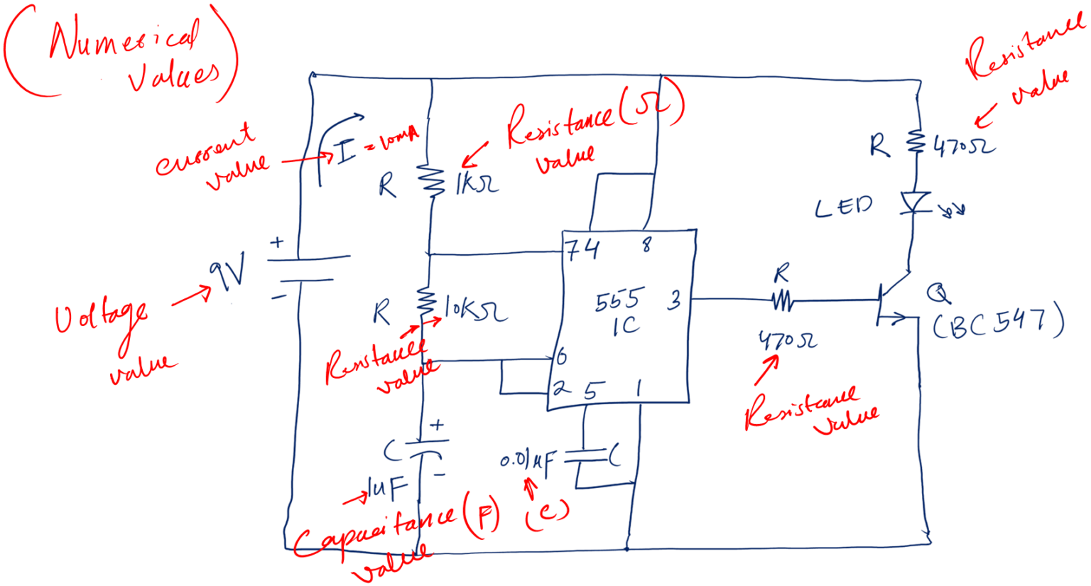
In real situations, we need these values to be measured before we put them in our circuit. Because we can’t randomly put any component.
The circuit will not work.
So, to measure these values, we need a measuring tool called the multimeter.
A multimeter is a measuring device used to measure the following quantities.
- Resistance of a resistor
- Capacitance
- Voltages
- Currents
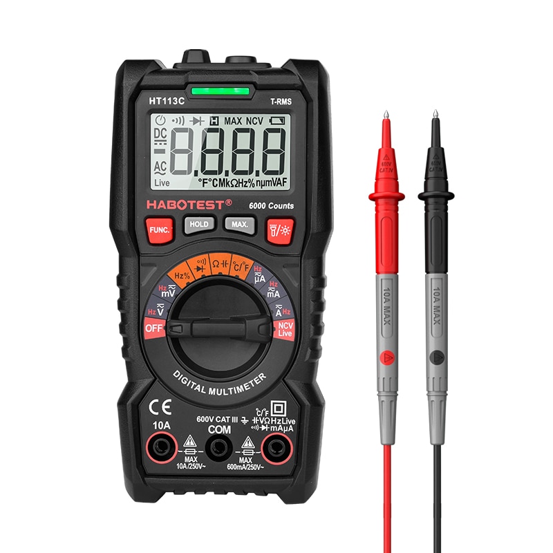
In every multimeter, there is a dial or the nob, called the selector switch, using which you set the range.
For example, you want to measure the voltage. All you need is to set the dial to the symbol of V and get the results on the display.
3. Component tester
The next tool is the component tester. This tool determines if the component is bad or good.
For example, if you have a resistor. How would you one if it is a good or defective one? The answer is to use a component tester like the below M328.
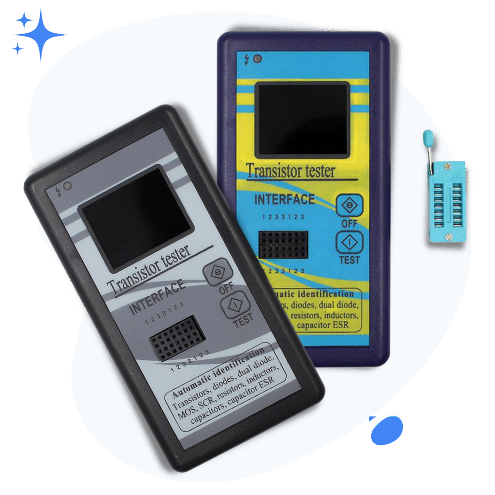
All you have to do is just put the resistor, capacitor, or transistor into the M328. Press the test button. And see if your respective component is ok for use in the circuit.
4. Component kit
This is very obvious. By component kit, I mean you need to have the actual set of components according to your circuit diagram.

Since every circuit project you will work on will be different. So I believe a component kit covering a range of components would be an efficient way to go with it.
Making your First Flashing Circuit (Step by Step)
I am so excited about this section because, for many of you, this is the design of your own first circuit.
So far, we have seen the circuit diagram of a flashing circuit. Now, it is time to make that circuit on a breadboard.
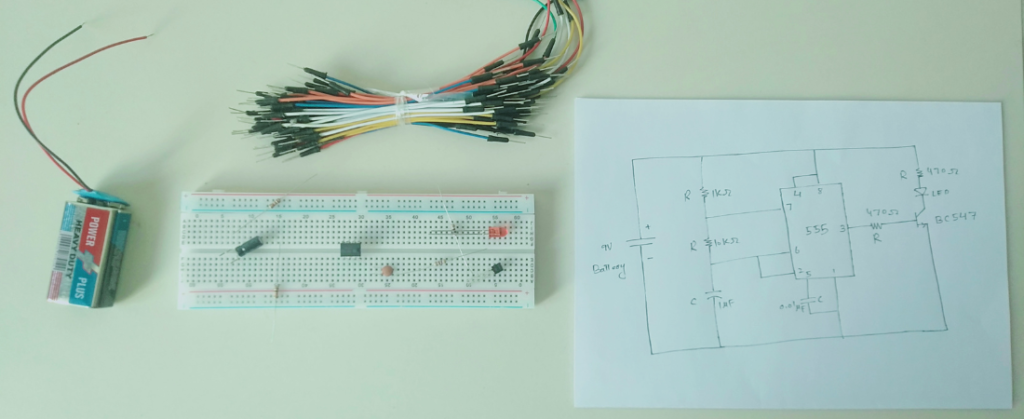
The following are the devices and circuit components that we will use to make our circuit.
Don’t worry, I will guide you step by step.
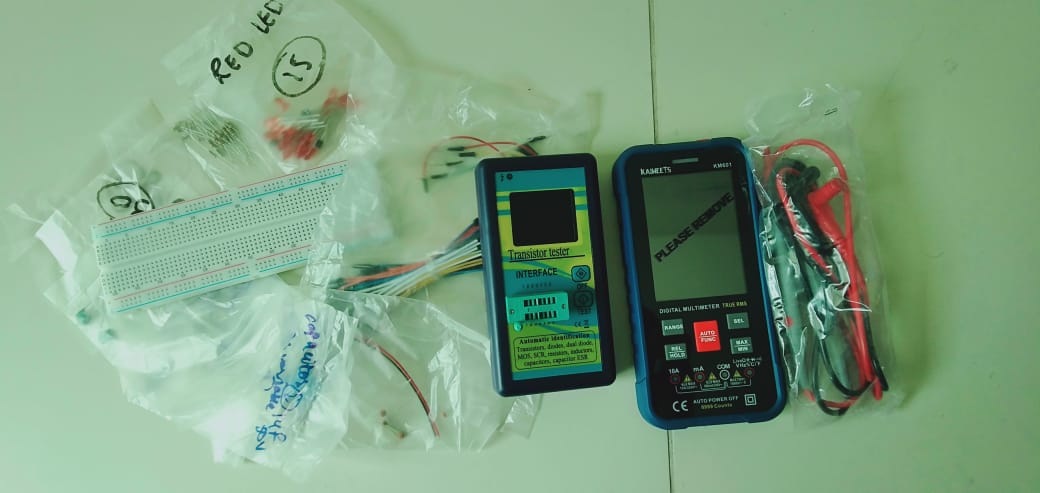
On the right, we have circuit components and a breadboard. On the left, we have a multimeter and component tester.
Step 1: Separate the components
If we see our circuit diagram of the flashing circuit. We would see we need the following components. To verify the values of the component, we would use a multimeter.
Starting with 1k Ohm Resistor:
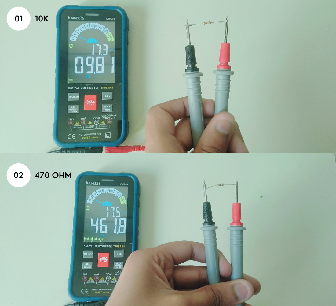
For resistors, we will use a multimeter.
- First connect the multimeter probes as below: Black probe to COM and Red probe to the Ohm port.
- Then select the resistance mode on the multimeter and connect the resistor like below.
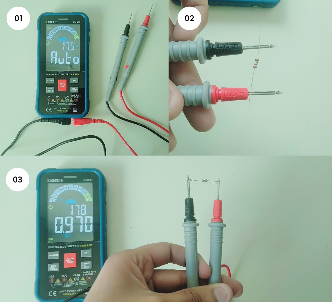
- Note down the results
Repeat the same process for 10k and 470 resistors:
See the following pictures for your reference.
Checking the electrolytic capacitor (1uF) and ceramic (0.01uF):
For this, we will use our all-in-one component tester. This tester will help us measure the capacitance value as well as give us the right pins (cathode and anode) of the capacitor, which is very important.
- Take your capacitor and completely discharge it by shorting its legs
- Then put that capacitor into the component tester as shown below
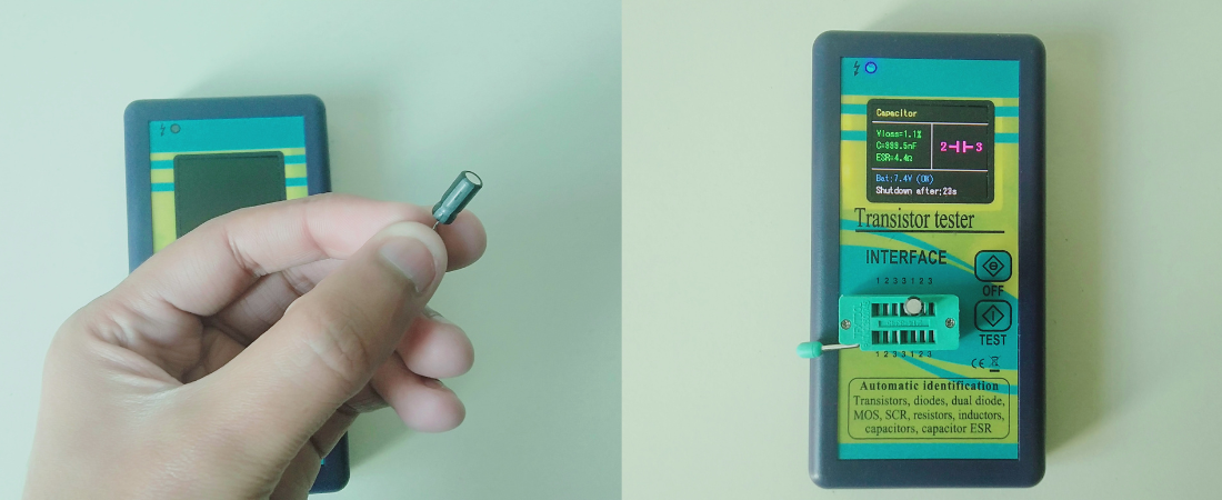
- See the results and correct pin configuration of the capacitor
- Please note down the pins
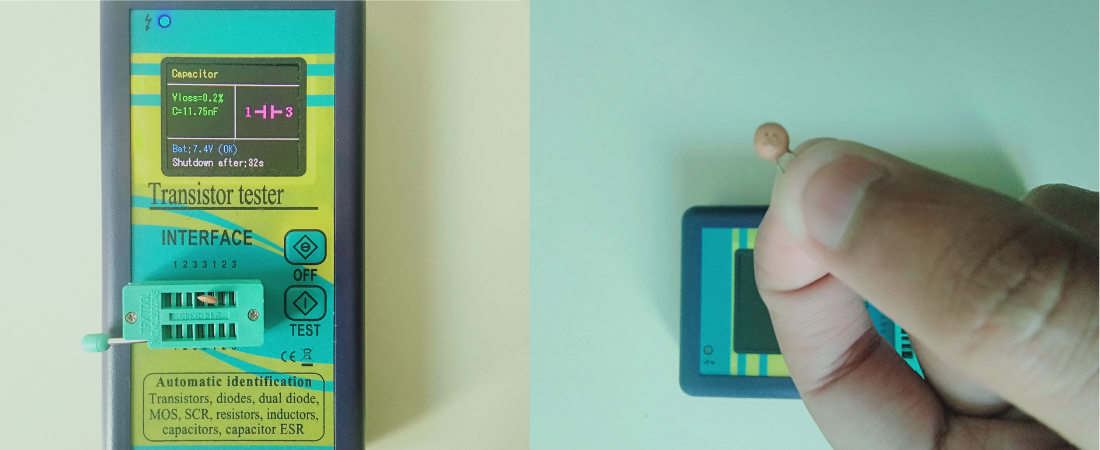
The same steps go for the ceramic 0.01uF capacitor as well.
LED testing
To find the anode and cathode of an LED, we will use our component tester. The tester will also tell if the LED is fine or a bad one.
- Take your LED and put it in the component tester
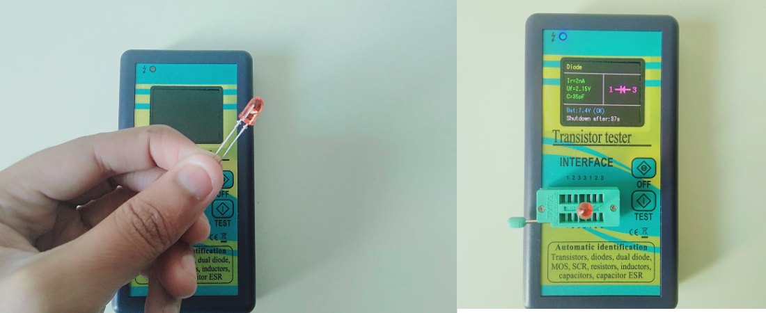
- Press the test button and see the results on the screen
- Please note down the pins of the LED
Just in case you don’t want to use any device for the pins, then remember the edge side of the LED is the negative terminal.
Transistor checking
In the case of a transistor, we need to find out which pin is the base, collector, and emitter. For this, we will again use our component tester.
- Take your transistor and put it in the component tester
- Press the test button and see the pin configuration of the transistor
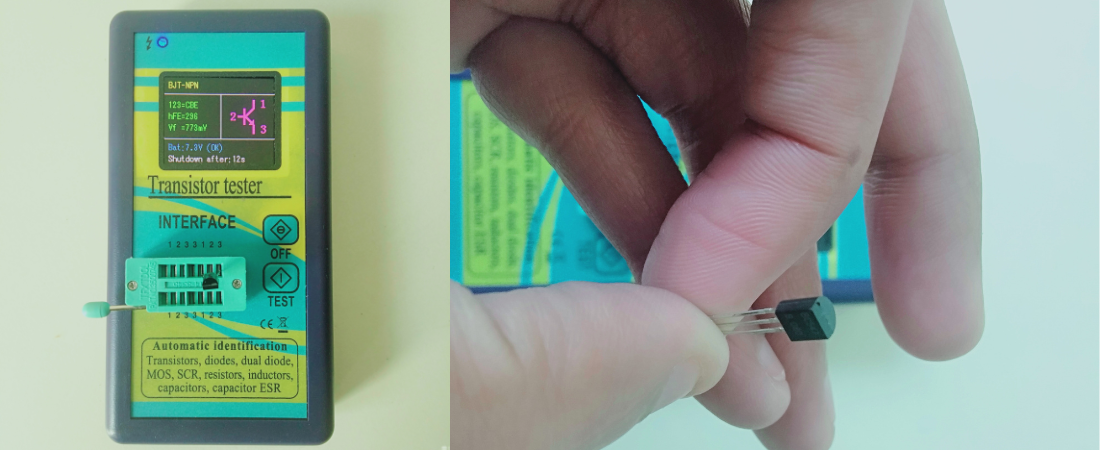
- Please don’t forget to note down these readings
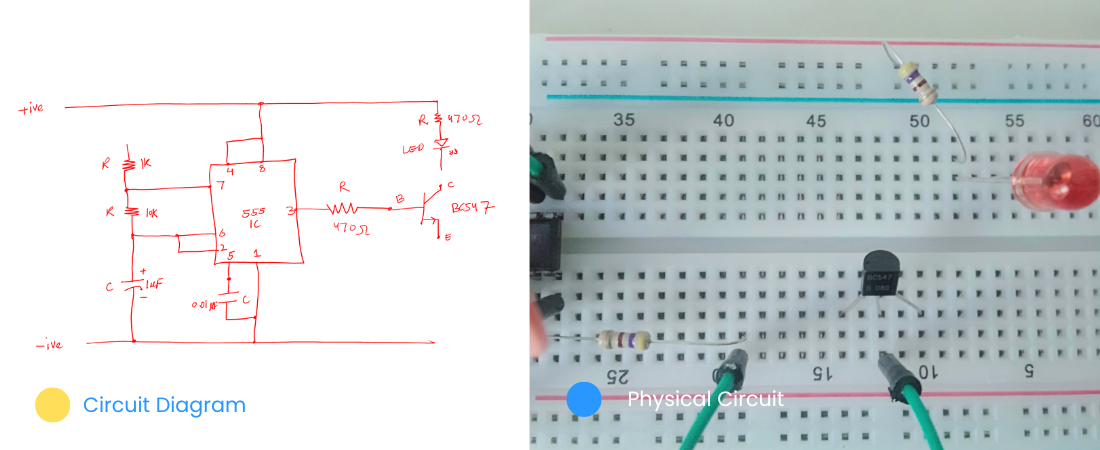
Finally, we have successfully measured our components. The following is the circuit diagram with their real-time circuit components.
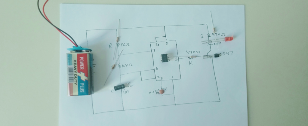
The next task is to make this circuit on the breadboard.
Step 2: Making the circuit
For this step, please print out the circuit diagram or draw it by hand. I would recommend drawing it by hand, as it will help you remember the connection more effectively.
Take a breadboard, printout, connection wires, and all the components.
Let’s get started.
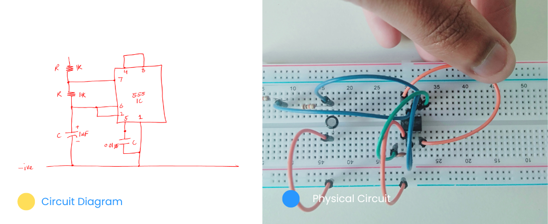
Firstly, start with the 555 IC.
- Take your 555 timer IC.
- Spot out the notch as shown below
- From the left to the notch, start counting the number of pins
- Then put the IC on the breadboard as below.
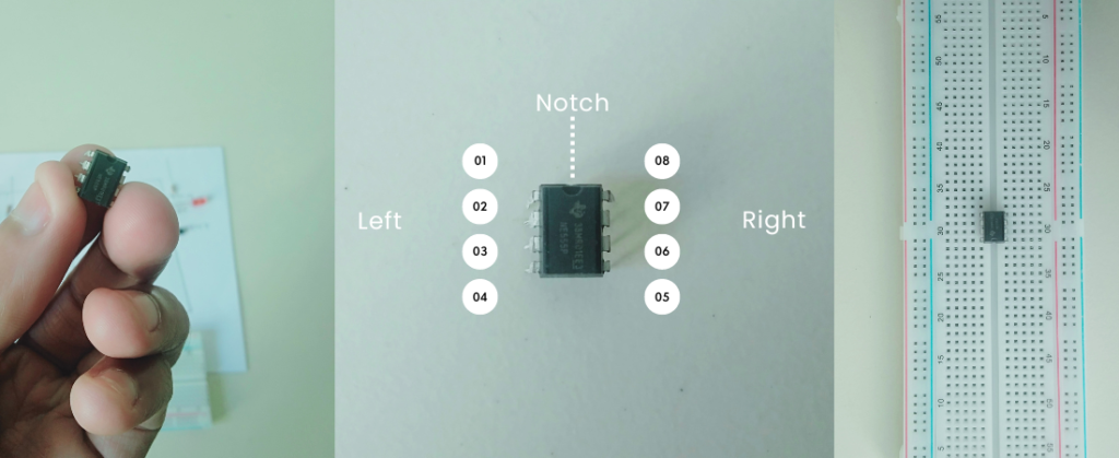
- Don’t put the IC anywhere else on the breadboard, this is a really important point to always remember
Start making the connections
After the IC placement, keep the circuit diagram on the side and start making the connection exactly according to the diagram.
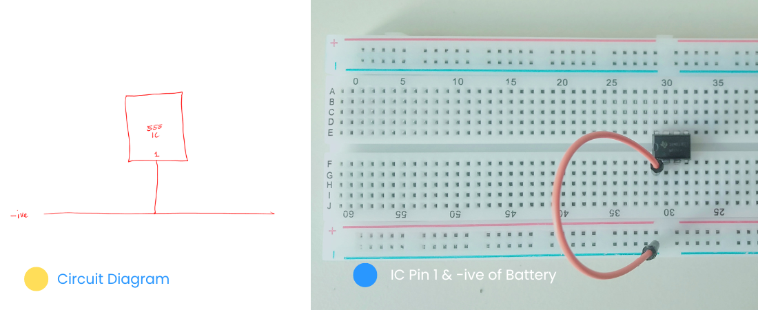
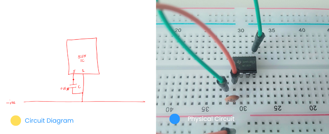
Connect one terminal of the 0.01uF ceramic capacitor to IC pin one.
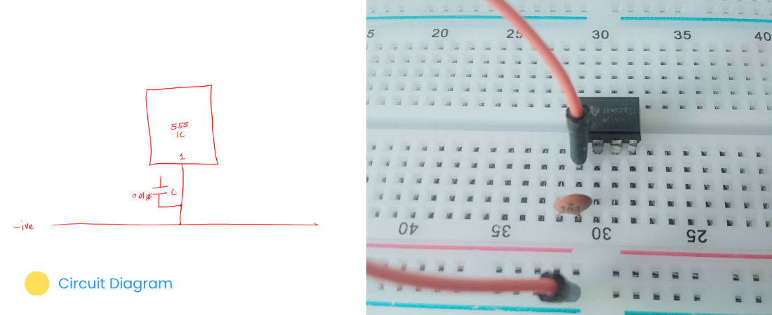
Connect the other terminal of the 0.01uF ceramic capacitor to IC pin five.
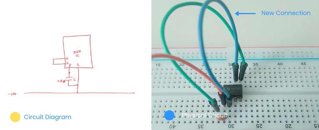
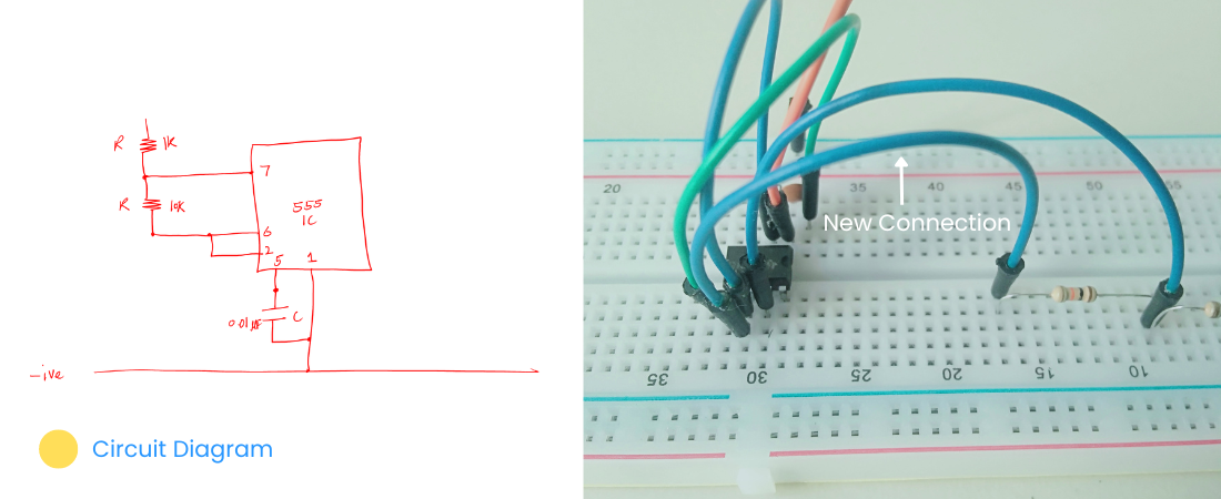
Connect IC pins 2 to 6 (short pins 2 and 6 together).
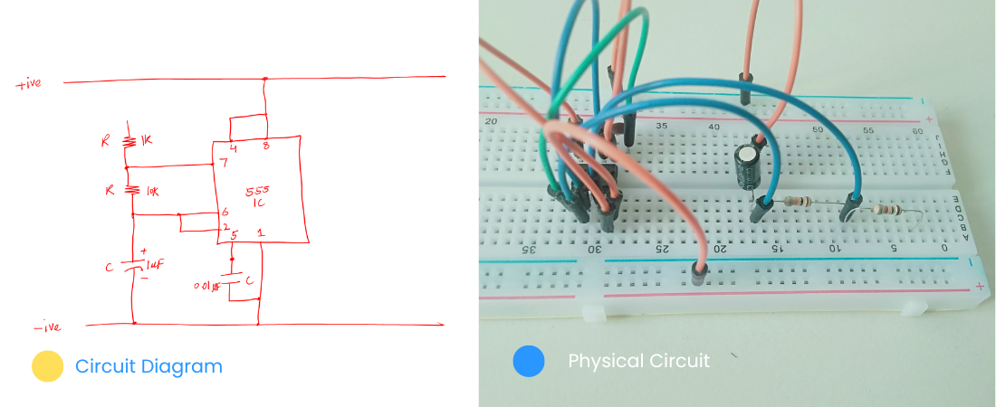
Place the 10K and 1K resistors.
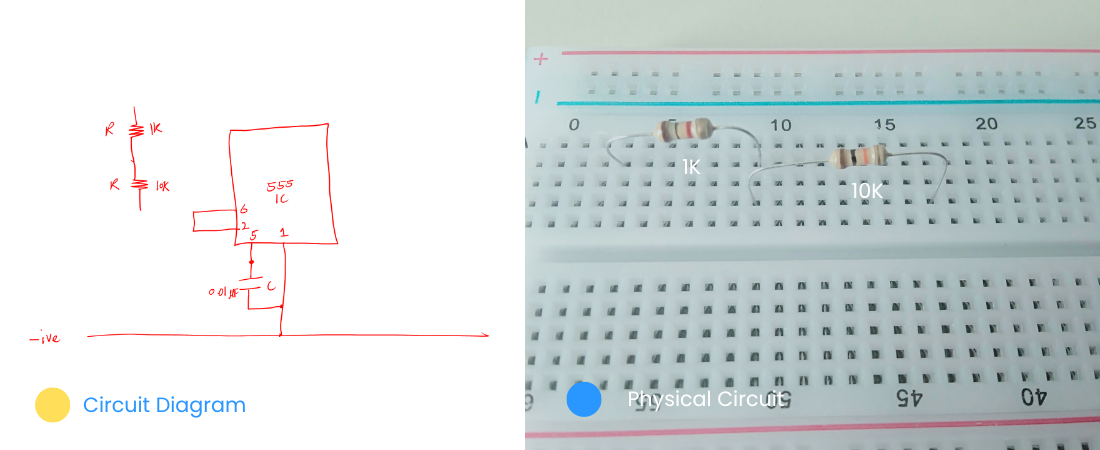
Connect IC pin 7 to the common connection of the 1K and 10K resistors.
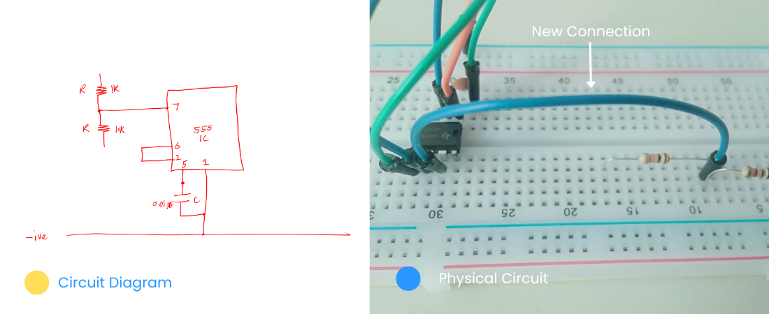
Connect the other terminal of the 10K resistor to IC pin 6.
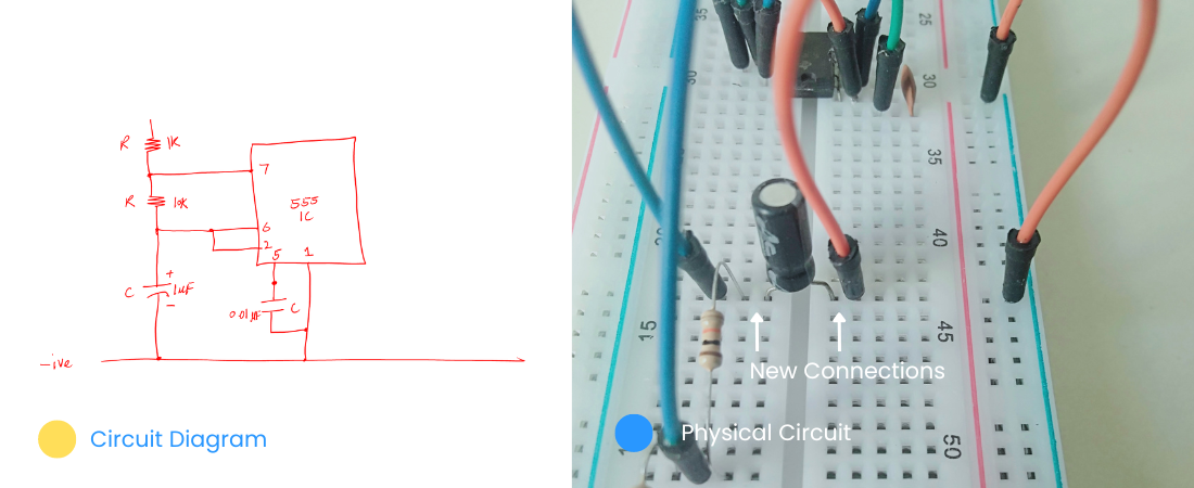
Place the 1uF electrolytic capacitor. Connect its positive (anode) to the short terminal of 10K and IC pin 6. Then connect the negative (cathode) terminal of the capacitor to the negative terminal of the power supply.
Short the IC pins 4 and 8, I mean connect them using the connecting wire.
Connect the shorted pins 4 and 8 to the positive terminal of the power supply (9V battery).
Connect the 470 Ohm resistor to IC pin 3, the output pin.
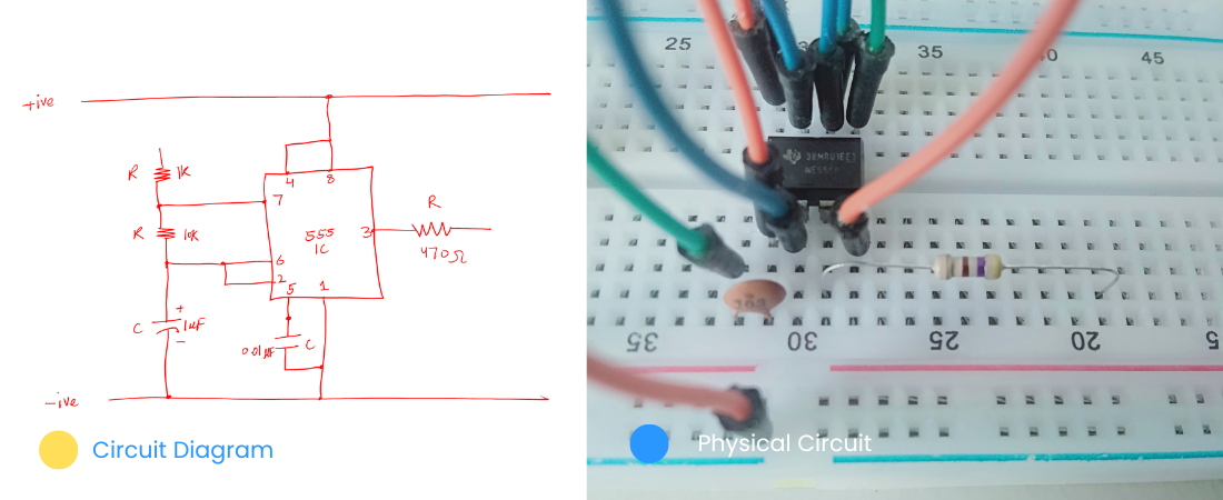
Now, coming toward the LED side of the circuit. Look carefully at the circuit diagram.
First, connect the 470 Ohm resistor to the positive terminal of the power supply (9V battery). Then to the other terminal of that resistor connect the positive anode of the LED as shown below.
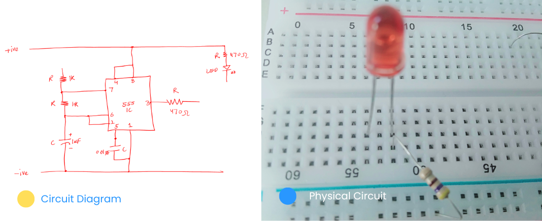
Next is to place the transistor. Please don’t put a transistor in the same row. Always put it as shown below.
Connect the base (B) terminal of the transistor (BC547) to the terminal of the 470 Ohm resistor.
Connect the collector (C) terminal of the transistor to the cathode terminal of the LED.
Connect the emitter (E) terminal of the transistor to the negative terminal of the power supply.
Just to give you a little extra knowledge, any breadboard has the upper power rows disconnected after 5 slots (you can see the upper lines are disconnected).
In the following, I just shorted the upper row so that we can have a power supply on the entire upper row (the + one).
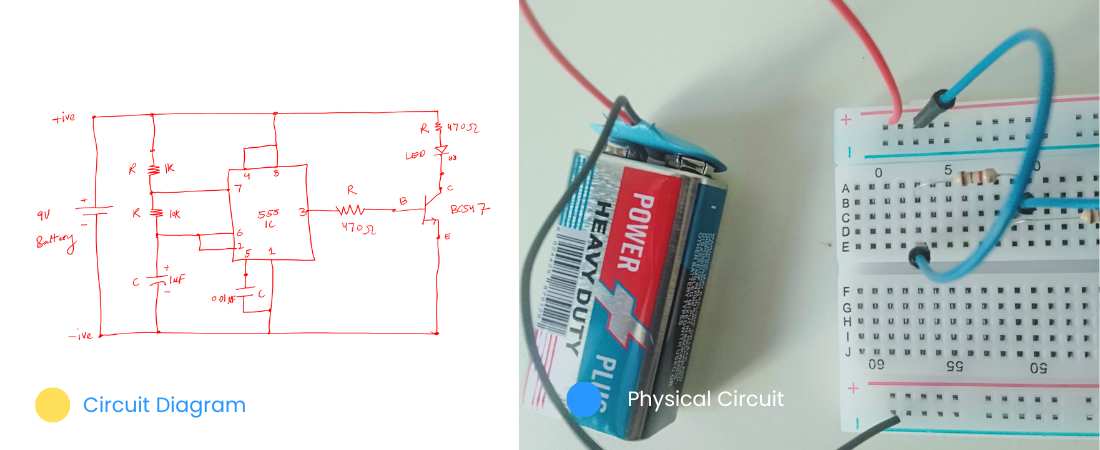
Next, connect the terminal of the 1K resistor to the positive terminal of the power supply. With this, we have finally made our entire circuit diagram.
Connect the power supply. We have a 9V battery as a power supply. Connect the positive (red wire) to the upper positive row of the breadboard.
Connect the negative of the 9V battery to the lower negative row of the breadboard as shown below.
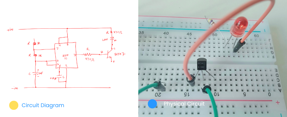
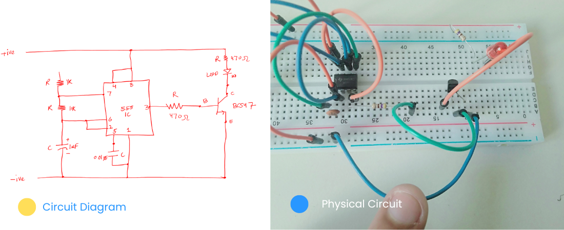
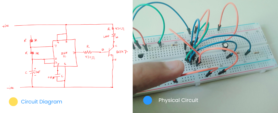
Step 3: Completing the circuit
With that, we have finally completed our circuit. Following is the final version of our circuit. This is a replica of our circuit on paper.
Enjoy your hard work so far; you made it.
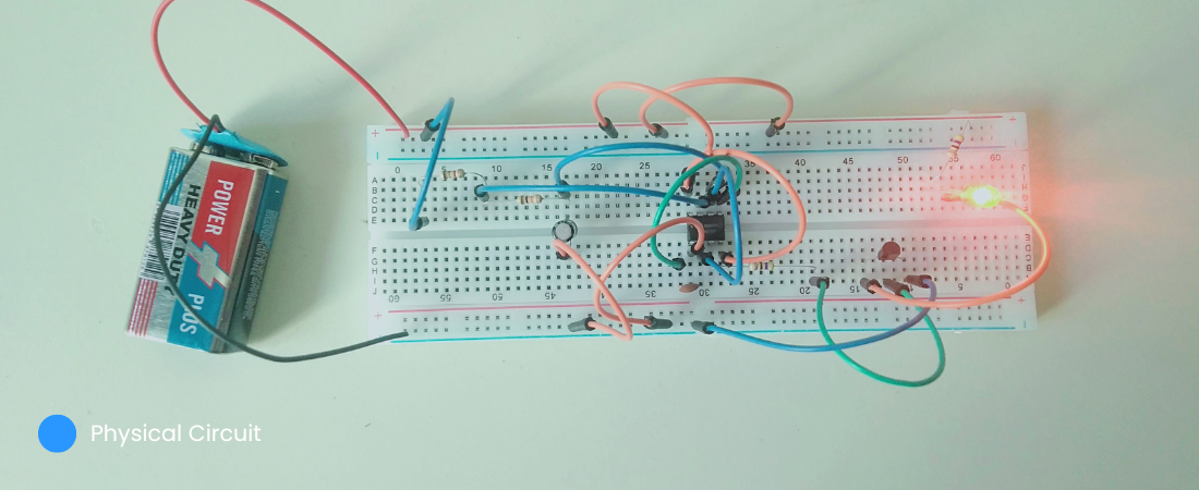
If you follow everything above, then you should be able to have a working flashing circuit.
Important circuit cases
We have successfully made our circuit. It works fine.
But what if you make a circuit, and it does not work the way it is supposed to be.
Then what?
Following are the possible cases that may go wrong. And when you fix them, chances are your work will work fine then. This process is called is circuit troubleshooting.
1. Open circuit
Now, let me ask a question. What will happen if I remove one of the connecting wires or any circuit component from the circuit?
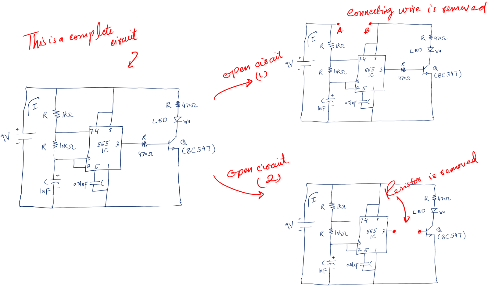
The simple answer is that the circuit is not complete anymore. And an incomplete circuit is called an open circuit.
Or more technically speaking any two points on a board or circuit that offer infinite resistance (R), we call it an open circuit.
Mathematically:
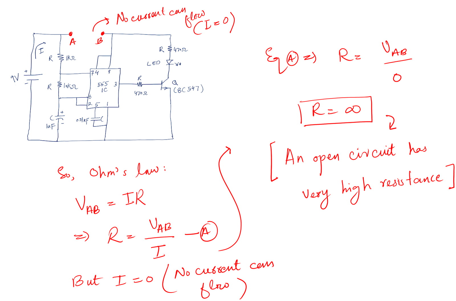
By applying Ohm’s law we can clearly see that any circuit points that offer very large (infinite) resistance will be treated as open circuit points.
The interesting facts about open circuits are:
- There can be any voltage value across the points i.e. for example in the above picture point A and B have any voltage value.
- No current flows through the open circuit whatsoever.
So, if your circuit is working fine. Check for open circuits. If any points are making any open circuits, fix them immediately.
2. Short circuit
Opposite the open circuit, there is a short circuit.
Technically speaking, any two points on a board or circuit that offer zero resistance are referred to as a short circuit.
Like in the above circuit case, we plug out the connecting wire making an open circuit. In the short circuit, we will put the connecting wire back.
Mathematically:
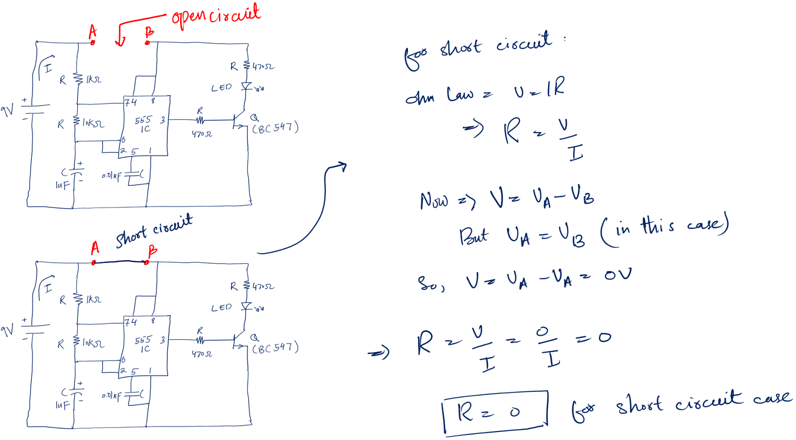
When we apply Ohm’s law to the short circuit we end up with zero resistance.
The following are things you should keep in mind about a short circuit.
- The voltage difference across a short circuit is always zero
- Any amount of current can flow into a short circuit. And this is the reason we often hear a building catching fire because of an electrical short circuit.
Now we combine two components by shorting their terminal to one another, this is good and this is how we connect components.
But if we short the connection between the two terminals of the same device we might end up damaging that device.
Conclusion
Learning basic electronics for beginners is like getting your first step into a huge ocean of the electronics world.
It needs dedication and full focus to know and understand the concepts. Once you get the basic concepts, the rest will make sense to you.
In conclusion, it is all about getting to know the definition of electronics.
To fully understand the definition, we need to first understand the concept of electricity, then based on electricity, we differentiate among different materials like,
- Materials that allow electricity to flow through them are called conductors.
- Materials that don’t allow the flow of electricity in any case are called insulators
- Semiconductors: They are in the middle of both insulators and conductors. They partially allow the flow of electrons (electricity) and partially block.
We define electronics as the study of the motion of electric charges (electrons) through semiconductor devices. Because of semiconductors, today’s modern world is possible.
Once we get the idea of electronics, we then talk about some basic terms used in electronics all the time, i.e., voltage (V), current (I), and electrical resistance (R). These terms are related to each other by a very famous law, called Ohm’s law.
Ohm’s law says that the voltage across the two points in the circuit is directly proportional to the current flow through that device. We use this law all the time in circuit analysis and the design of various electronic systems.
Then we start talking about beginner electronics components and circuits, and then at the end, we try to use our learning and do a project: the LED flashing circuit.
Along the way, we also get to know what is breadboard and multimeter, and how these guys help us in learning electronics.
I hope you enjoyed this article and that my little effort kinda helped you. If you want to get into more details, here is my book for you: Make Your First Electronic Circuits.
Thank you!
**These were some basics of electronics a beginner must know if he wants to get started with electronics in the right direction. You can go ahead with these basic electronics books for further in dept details.
simple but very educational loved the way you did it with drawings so much easier to understand thank you so much
Welcome 🙂
very helpful…..thanks
Welcome 🙂
Thank you, I appreciate this.
Welcome
ABBAS, I am indeed very fortunate to hit this site and i’ll tell you why. i am a post graduate mechanical engineer who has just turned 77 with a passionate interest in mechatronics. i did not know where to start to understand the basics of practical electronics and i have found it on your site. Thank you. i think you should put it all together and publish a book titled ‘Practical Electronics’.
Thank you so much
Very helpful ..thank you.. i could understand it so effectively
Thank you so much