

Multimeter Basics: Everything beginner must know (2026)
The multimeter is one of the basic electronic tools for safely measuring current, voltage, and resistance. You must have a little bit of an idea of a multimeter when learning your course, from a teacher, or from whatever place.
The multimeter is a tool for assessing various electrical parameters within a circuit. The primary functions of a multimeter include measuring voltage, current, and resistance. Multimeters come in two main types: analog and digital. Analog multimeters employ a needle and scale display, providing a visual representation of measurements, while digital multimeters present precise numerical readings on a digital screen.
In this article, we will explore the basics of a multimeter and explain its various features and functions in detail.
Multimeter basics
By multimeter basics, we actually mean what is multimeter and how we can use it to measure certain electrical quantities.
Now we know that there are many electrical quantities to measure but the specific ones that we can measure with a multimeter are the voltages, currents, and resistance.
When I say voltages or currents measurements I mean both alternating and direct (constant) voltages and currents (AC and DC). A multimeter can measure both of them with greater accuracy depending on manufacturing quality.
A bad multimeter is a waste of time and money and if you are using it for high voltages it can be deadly dangerous as well.
I use the word deadly dangerous not to scare you but to remind you of safety.
You know, voltages are dangerous when the levels are high. But technically, AC is far more dangerous than DC. I am not saying DC is safe.
I am saying this because, usually, we deal with high amplitude or levels of AC most of the time. While we play with small value DC most of the time.
In our home sockets, we are getting AC which has a value of 110V/220V depending on the country you are living in. While your car battery or battery on your mobile phone is DC.
Step 1: What is a multimeter and why bother?
Imagine you brought an expensive device to your home. You can suppose it as a time machine, just kidding. The specifications of the device say you must power it up with 110V else you may end up damaging it. Right!
So, you are the guy that just doesn’t know what the hell that means. You are worried that the device is pretty expensive.
What you can do?
You call a nearby electrician to check the socket voltage for you or you decide to learn how to handle such situations, and you decided to learn it yourself.
And let me tell you, you can definitely do it. It is so simple.
The situation may differ, there can come the time you will need to measure current, or resistances.
Let for the sake of simplicity we call these quantities i.e. voltage, current, resistance, the electrical quantities.
My point is you may encounter the said situations where knowledge of multimeter basics would help you.
Multimeter is an electronics device we use to measure various electrical quantities.
Now let’s talk further.
You know, let’s imagine another situation. You are at home. Everything is fine but the electrical socket next to your bed is not charging your mobile phone.
The possibility is your phone is bad, or the charger is bad, or the socket itself is bad and acting fishy. How would you know that? How do troubleshoot this situation?
Or think of your car battery diagnosis. How could possibly do it by yourself? The answer is to learn how to use a multimeter. So, the complete definition can be as follows.
Multimeter is an electronics device we use for measuring electrical quantities and troubleshooting devices.
We can use a multimeter for troubleshooting PCB boards, and for circuit continuity testing as well.
Besides the fundamental quantities i.e. voltage, current, and resistance. A multimeter can do a lot more than this. These are called the extra features.
We buy these features according to our project requirements. Like you also want to have a capacitance measuring feature in your multimeter, hell yeah, you can have it.
In summary, your multimeter can do the following if you decide to pay for it as well.
- Circuit continuity test
- Transistor testing
- Inductance measurement
- Capacitance measurement
I find circuit continuity the must-have because you will use it a lot when working with circuit prototyping or PCB traces troubleshooting.
Now, you can imagine your own situation where you can apply the knowledge of beginner multimeter basics and solve it properly.
Let say you have a battery i.e. remote battery cell. You measure its voltage, it’s 1.5V. Now, what will be its voltage when you connect two cells in series and parallel. Think about it.
Step 2: Different parts of a multimeter
You know, the multimeter may be of different shapes and sizes, but these things don’t matter. You will always identify the basic parts and these parts are common in each and every model out there.
Let take a look at the following multimeter and identify which part is which and what each part is contributing to the whole function of the multimeter.
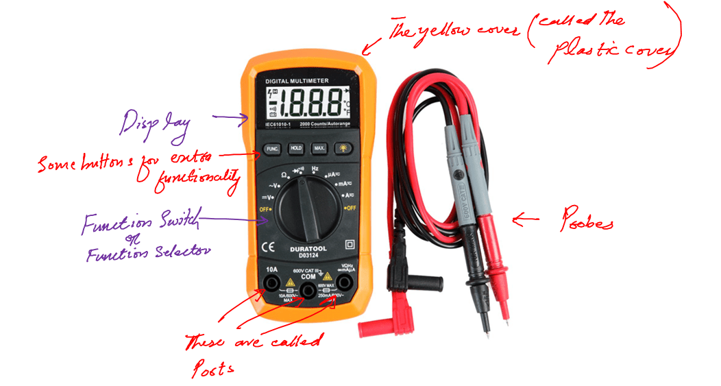
Following are the parts you may have noticed:
- Display
- Probes
- Ports
- Function selector
- Extra function buttons
Let’s talk about these parts in a little detail.
1- Display
Starting with digital display. As the name is telling the whole story, this part of the multimeter shows us the results which we then note down for our record.
2- Probes
These are the connecting cables we use to connect the device which we want to measure to the multimeter. The quality of probes must be high else you will have some errors in your readings.
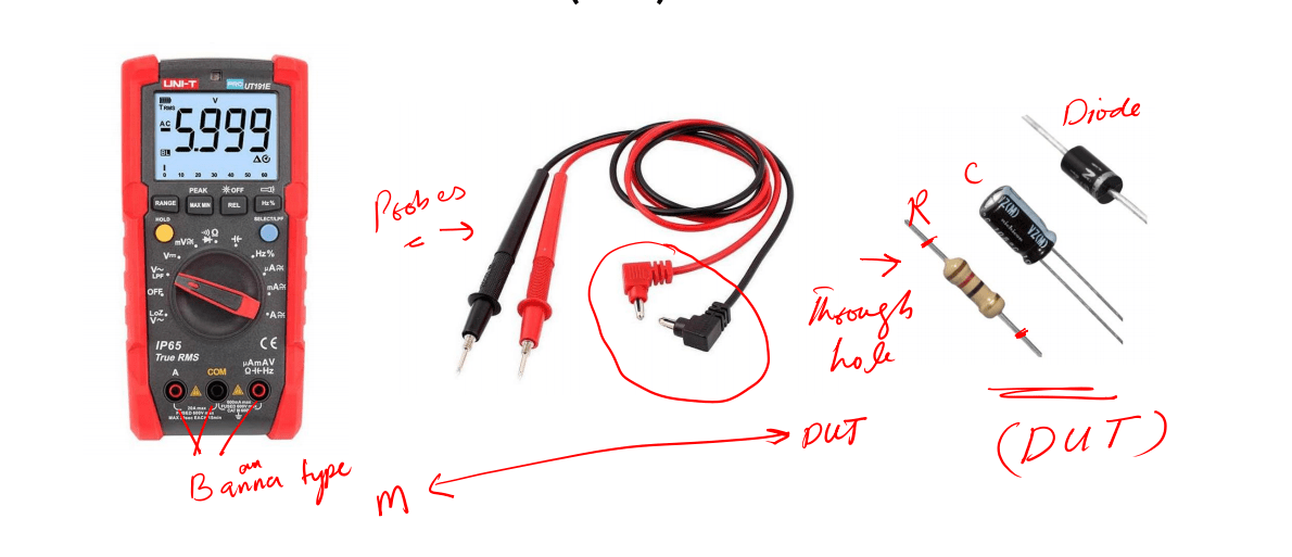
The device we want to measure may be a resistor, capacitor, and many others.
So we generally call the device we want to measure, the device under test (DUT).
Now the DUT may also be sometime through-hole devices or maybe you deal with surface mount devices (SMD).
So the pair of probes you are working for one situation may not be efficient for other sets of arrangments and situations.
Therefore we have the following different types of probes for certain situations.
Banana plug to simple test probes:
These are the default probes for a multimeter. Every multimeter comes with these probes.
These are best for through-hole components. But we use it for other purposes as well.
Banana plug to alligator clips:
These probes are best used when we are dealing with constantly monitoring a certain quantity. W
e also use it for situations such as car battery diagnoses and many more. The main purpose of these probes is to make our hands free.
Banana plug to IC hook:
These are used when we work with electronics circuit boards.
Banana plug to tweezers:
They are used to measure SMD components effectively.
You may notice that all the probes are banana plugs to the others that is because every multimeter has an input banana plug.
Keep in mind that you should always use a decent pair of probes. If you have a banana plug to simple test probes that is enough for you, but it is good to have the other as well.
3- Ports
The number of ports and their arrangement may be different for different models of multimeters.
But they will always be the connection points through which probes will get connected to the multimeter internal circuit board.
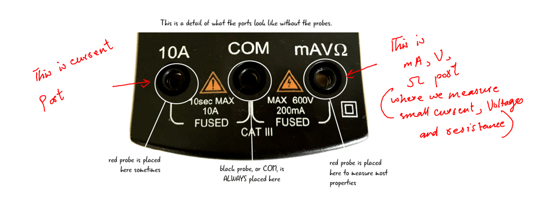
So it doesn’t matter where a port is just remember, COM is the port where the black probe will be connected always.
The red probe will be put into the V port if we want to measure voltage, into the Ω port if we want to measure resistance, into the mA port if we want to measure small resistance, and into the A port if we want to measure large currents, and you get the idea.
4- Function selector
A multimeter is named this way because it can do multifunctions.
So to select among the different functions of the multimeter i.e. to select voltage, current, and resistance measurements, we use around a big button called the function selector button.
The job of the function selector (dail) is to set the multimeter into voltage, current, and resistance measuring mode. Sometimes it is also called a selector switch.
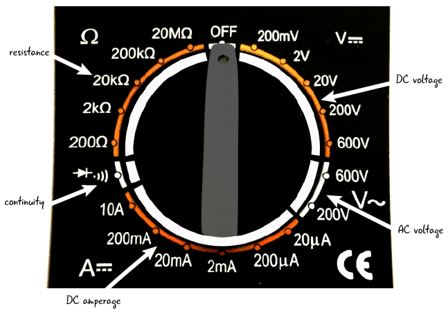
We align the selector switch to the function we want to measure. There is always a little pinch on the selector switch which helps us in aligning.
For example, in the above picture, the selector switch’s circle pinch is aligned to the OFF, which means the multimeter right now is in the OFF state.
Align multimeter to V∼, which means multimeter is in AC measurement mode. Align it to the Ω sign and your multimeter in resistance measuring mode.
5- Extra function buttons
These buttons do the extra work for us. And these buttons are totally manufacturer dependent.
Like I can’t say every multimeter has these buttons. Some of the multimeters may have one of these buttons. It is up to you how much you pay for extra functionality.
These buttons have nothing to do with measurements. They just do little extra cool things for us which is sometimes very helpful.
For example, a hold button is used to hold the reading for you. So if you are working in the field and you can see the screen properly, all you have to do is make the connection and press the hold button.
And later on, when you are at ease see the screen and note down the reading.
Similarly, the peak button is used to show you the peak value in the signal.
Now, I can’t talk and list all the buttons. They are simple to understand. Every button is self-explanatory even if you are seeing them for the first time.
Step 3: Types of multimer
There are different types of multimeters out there. They do the same job, the difference occurs because of the work environment and demand for a certain set of measurements.
For example, if you work in a lab and your job is to test small DC voltages and measure some load resistances, then a normal digital type of multimeter would be good for you.
But if are a field engineer or electrician and you do high voltage and current measurements then a clamp meter, which we will see shortly, would be the preferable choice for you.
We will go through all the available types of multimeters and then it is up to your work requirement which type might be the best suit for you.
1. Analog multimeter
This is the first and old type of multimeter. Currently, most field professionals don’t use it that much but hay it can still be used for certain measurements.
For example, if you are doing some tuning measurements this guy is good for you. But if you want more accuracy and a user-friendly device then this device may not a good choice for you.
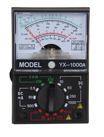
Now some of you may haven’t seen this meter before. Isn’t cool?
The parts are the same as we discussed above. The only change that can be seen is the display. This type of display is called the analog display.
And this display is the real problem with these meters like it is hard to read them and say the accurate readings.
Let’s see the good thing about this guy:
- Requires no battery, you can use it for life long without worrying about its batteries.
- It doesn’t overheat, which is a really good feature about it.
- Reading the fluctuating signals – it doesn’t average the fluctuating signal so you see and analyze the full swing of such signals.
- It has high input impedance making it good for measuring current, so you can say it is a good Ammeter.
- And it doesn’t cost too much as compared to the other types.
If you are thinking next I will talk about the bad features of an analog meter. That is not going to happen!
The good features of the coming types will be the bad features of this guy automatically, and the above good features of this guy are the bad features of the rest of the types.
2. Digital multimeter
Everything you need is in the name, digital. This type of meter uses digital technology.
We really don’t need to understand the digital engineering of it but it is good to know in general. These meters convert the coming analog voltage and current signal into digital, process it, and give us as accurate results as possible.
So in summary there is some analog to digital converters (ADC) involved in the making of these meters.
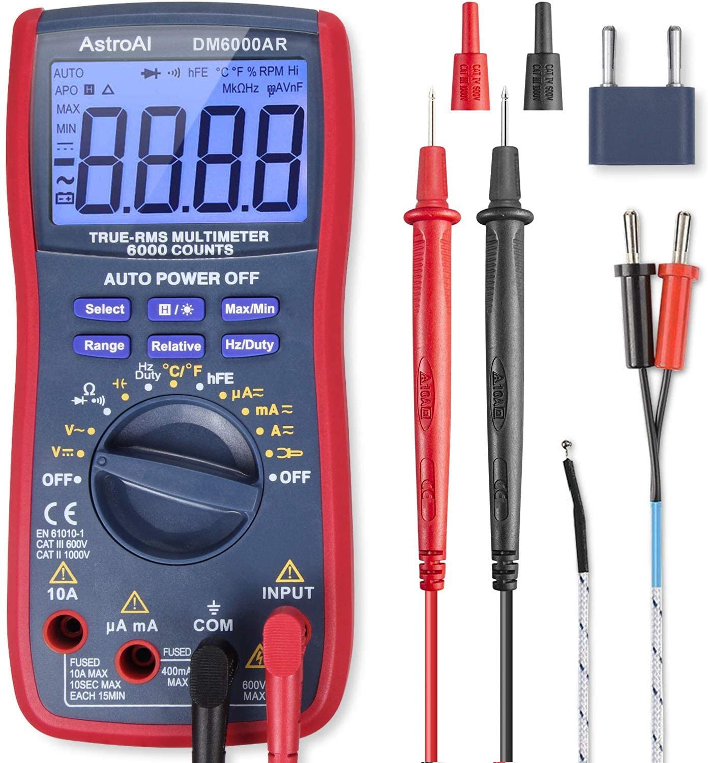
This is the picture of a digital multimeter. You may notice it right off the back, the display. This display is digital and easy to read as compared to the above analog display. You know, you just need to read the number right away.
Now the display is not the only game-changer, let’s see what else this digital guy got for us. (These are bad features for analog meter)
- More accurate results because we don’t need to read the analog display
- Auto polarity detection. This means if you connect the probes reversely you can have accurate readings. But using the analog meter if you accidentally reverse the polarity you damaged the meter.
- If you drop this guy (assuming not from 5 story building) this guy will work accurately.
- Today’s modern meter comes with automatic range detection. All you have to do is just plug the probes and you get the results.
- Have additional useful features such as holding the results, measuring the peak voltage, and bright display light to work at night, or in dark sight.
It seems like if a beginner decides to pick a meter, it should be the digital one unless he is sure what he is doing.
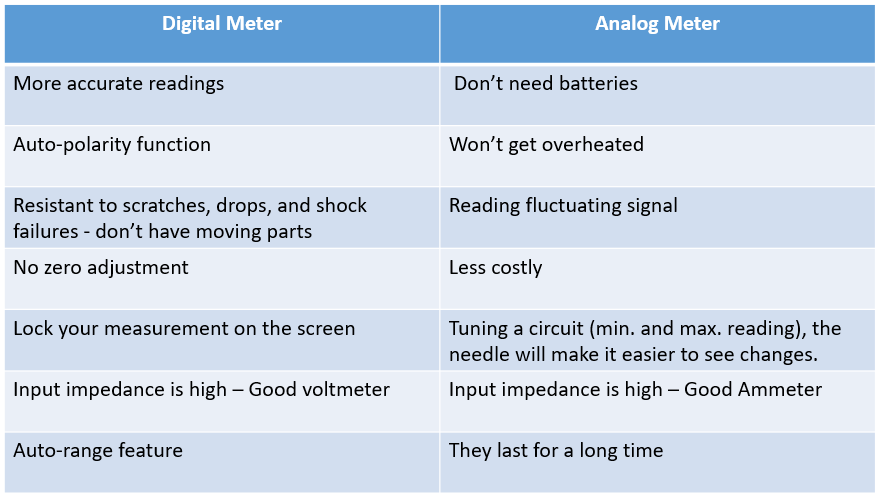
For your reference, this is the comparison table for analog and digital meters.
In this multimeter basics learning, the first part is to decide what meter is right for which measurements.
Now you learned about the two types and should have an idea which meter is going to be best for which measurements. In case you are still confused, my recommendation is to go for a digital multimeter.
2. Auto and manual range digital multimeter
You got the idea of analog and digital meters. Now digital meters are sub-divided into two categories:
- Auto range
- Manual rage
They both do the same job. The difference is manual range meter is the old technology model while the auto range is the current state of the art technology.
The difference lies in the range selection.
Auto range selects the range automatically while in the manual one we have to select the range ourselves and try some different ranges to finally get the accurate results.
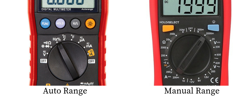
You can clearly see the difference. In the auto range, we just have to select the Ohm sign using the function selector round button.
While in a manual range we get the different values of Ohms and we have to manually select the range which we consider a good suit for our measurements.
4. Clamp meter
Sometimes we work in the field and deal with high voltage signals. These signals may be voltage signals and current signals.
There it is not easy and safe to go with traditional measurements. We need a safer multimeter, called the clamp meter. These meter uses electrical induction methods to measure voltages and currents.
Shortly we will see how to measure voltages by a multimeter. There you will have an idea why a clamp meter is a must tool if we are dealing with high voltage electrical circuits.
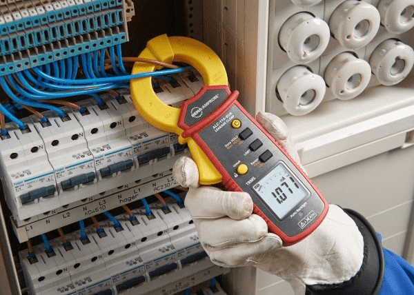
Clamp meters are digital meters except they are used in a different environment where safety is a priority.
They can measure voltages and currents both AC and DC. But they are specifically used for AC current measurements. It can also measure resistance and some other quantities as well.
Step 4: How to use a multimeter
Getting to learn how to use a multimeter is fun. Because it is so easy to learn.
All you need is dedication and full focus. Now, I recommend you should have your own basic multimeter. This would be great and you will repeat yourself what I am going to share with you onward.
A multimeter is used for two types of measurements:
- Standard measurements
- Additional measurements
Standard measurements include voltage, current, and resistance measurements.
Every multimeter has these standard measurement options. On the other hand, additional measurements include capacitance measurements, inductance measurements, continuity tests, transistor testing, and temperature measurements.
If you want to have some or all of the additional features you have to pay accordingly. The price of the multimeter depends on what extra functionality you want with it.
Let’s start with standard measurements.
1. Voltage measurements
Voltage measurement is one of the fundamental tasks in electronics. We need to get it right if we want to go successful in learning or practicing electronics.
The following are steps we take to measure voltages (AC or DC) by using a multimeter. These steps are common to every type of multimeter out there.
- Take your multimeter and probes.
- Check the probes for any bare wire, if you find out probes are a little damaged, get the new one right away.
- Place the device you want to measure voltage in a proper place. If you are working with live voltage and want to measure the voltage of the home socket and things like these then wear safety gloves first.
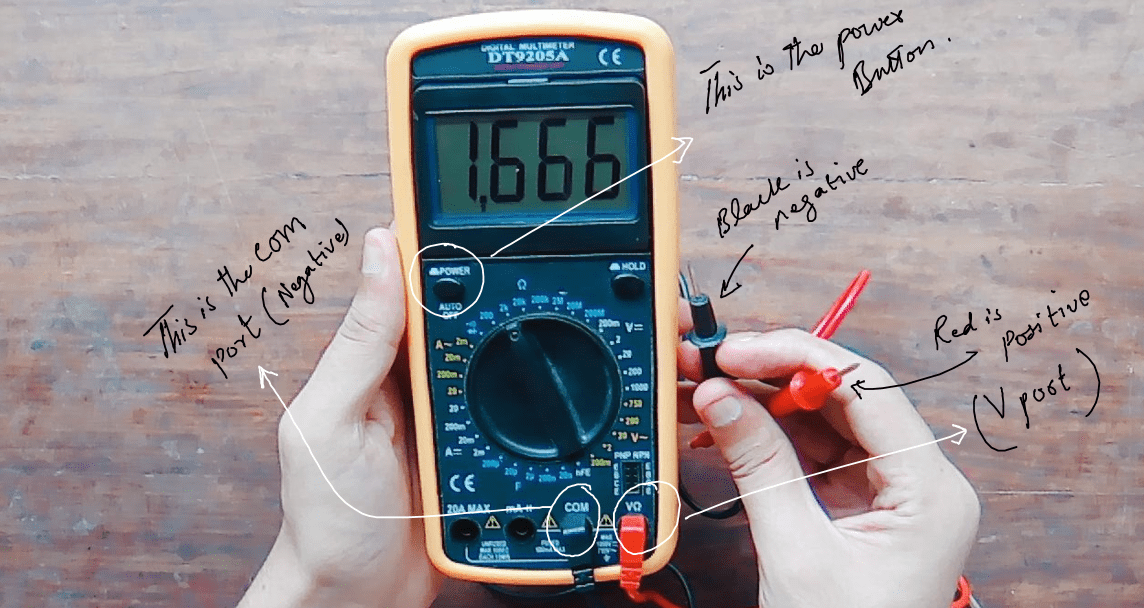
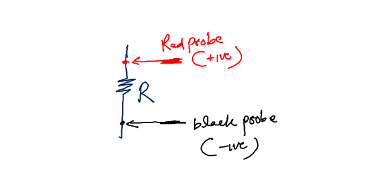
- Connect the black probe (Negative) to the COM port (A port in multimeter with written COM on it) and the red probe (Positive) to the V written port.

- Align the function selector button to the “V” sign/label. Now here is the trick. If you are measuring AC voltage then align the function selector switch to the AC voltage sign i.e. “V∼” and if you are doing DC voltage then align it to the DC voltage sign i.e. “V—”.
- Turn On your multimeter and look at the screen. If you are getting the zero value on screen it means your multimeter is good. But if you are getting some random values even your multimeter is not connected to anything else. It means your multimeter is bad, get a new one right away.
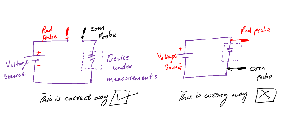
- Connect the probes lead to the device you want to measure voltage. Or connect them to the circuit points you want to measure the voltage across.
- In the auto range meter just align the function selector to the voltage sign (AC or DC) and get the reading immediately on the digital display. In the manual range, it is recommended to start from the lower range and go to the higher ranges unless you get the right results. The reason we start we a low range is because if your voltage value is bigger than the selected range you will get the reading of overload (OL) on the multimeter screen. This OL reading will vanish once you are in the right range.
- In the clamp meter, there are no probes all you have to do is to just grab the wires inside its upper jaw, select the Voltage function (AC or DC), and get the results on the display. Always wear protected pair of gloves when working with this guy.
Voltage measurement is straight forward but if you want more on this topic check out my below post. It might be helpful for you.
In the electronics circuit, voltages are measured across different devices in the circuit. So, it is good practice to buy different types of probes so that you don’t face problems while analyzing your circuit.
Lastly, never ever put a multimeter in voltage setting across the current source, it will damage your multimeter right away.
2. Current measurements
Current is the other basic electrical we want to measure in electronics all the time.
Most of the time we really need to know what current our load is driving or what branch in the circuit has how much of current, and the list goes on.
The important thing we should really know is that current is a load-dependent quantity.
So if we are measuring current, it doesn’t mean that this value of current will be the same forever.
No, this value will change once the load is changed. The end summary is if you want to measure the full current capability of a device or source connect the source to the rated load first.
And never ever connect your multimeter to a voltage source directly to measure its total current, you will blow up your multimeter for sure.
Now let’s talk about the step by step procedure that you can follow to measure the current accurately:
- Take your multimeter and probes.
- Check the probes, if they are damaged even a little, get a new one right away.
- Take the device you want to measure the current. Or take your multimeter to the place where measurements are to be done.
- Connect the black probe (Negative) to the COM port (A port in multimeter with written COM on it) and the red probe (Positive) to the “mA” written port.
- Now here is the thing, if you want to small current like below 1A, then use the “mA” port. But if you want to measure more than 1 A current, use the port with written “A” on it.
- Align the function selector button to the “A” label. A is used as Ampere, the SI unit of current.
- Here at this point, we do multimeter testing. After you connected the probes and set the function selector to the “A” label. Now power on the multimeter, and see the display. If there is zero reading this means multimeter is good. But if there are some random values and these values are not going anywhere after restarting the meter, well then your multimeter is faulty, get a new one right away.
- Connect the probes in series with your device. This is important, don’t put the probes across the device. See the following diagram for reference.

- Now if you want to measure Alternating current (AC) align the function selector to “A∼” or to “A−” if you want to measure DC.
- In the auto range meter just align the function selector to the current sign (AC or DC) and get the reading immediately on the digital display. In the manual range, it is recommended to start from the lower range and go to the higher ranges unless you get the right results. The reason we start we a low range is because if your current value is bigger than the selected range you will get the reading of overload (OL) on the multimeter screen. This OL reading will vanish once you are in the right range.
- In the clamp meter, there are no probes all you have to do is just grab the wires inside its upper jaw, select the Current function (AC or DC), and get the results on the display. Always wear protected pair of gloves when working with this guy.
So yeah this is all I got for you on how to use a multimeter for current measurements. At this point, I think we have got quite enough knowledge about multimeter basics.
3. Resistance measurement
You can read the resistance of a resistor by reading its color code. I don’t like this method. I clearly don’t remember every color all the time.
Yeah, that is one way to go but when you are working with so many resistors that method is pain. So we use a multimeter to do this job.
Measuring resistance value with a multimeter is very easy. Follow the following easy steps and you will be fine.
- Take your multimeter and probes, and check the probes. If probes are damaged even a little, get a new pair right away.
- Connect the black probe (Negative) to the COM port and the red probe (Positive) to the “Ω” written port.
- Align the function generator button to the “Ω” sign.
- Turn on your multimeter.
- Perform the following two tests to check if your multimeter is good for resistance measurements or not.
- Open circuit test: Leave the probes in the air untouched. If the reading on the display is 0l or l, then your meter is good else it is bad.
- Short circuit test: Place or put both probes together. See the readings. If the display is showing 0, your multimeter is good else it is a bad one and you need to get yourself a decent new meter.
- Your multimeter must pass one of the above tests at least.
- Now connect the probes across the resistor you want to measure the resistance value.

- Resistors are polarity-independent components to connect the probes any away. You will get the same results
- See the display, and read the results. It is that simple.
- For auto range multimeter: In auto range meter just align the function selector to the Ohm sign “Ω” and get the reading immediately on the digital display. In the manual range, it is recommended to start from the lower range and go to the higher ranges unless you get the right results. The reason we start we a low range is because if your current value is bigger than the selected range you will get the reading of overload (OL) on the multimeter screen. This OL reading will vanish once you are in the right range.
- We usually don’t use a clamp meter for resistance measurements.
If you want a detailed article on how to measure resistance by multimeter, then my below article would be helpful.
The important thing to remember is, always check your probes. Always make sure the probes are in the right place where suppose to be.
Like you are measuring resistance and your probes are in a large current “A” port in a multimeter. Guess what you will never get accurate results.
4. What else we can do with a multimeter
Oh God, what should I say now? We can do a lot of other cool things with a multimeter.
But I think the article says multimeter basics for beginners, so I should probably stop here.
Now if you are really curious about what else we can do, or how to use a multimeter for extra cool things. The following is just the summary.
- Capacitance measurements: We can use a multimeter to measure the capacitance of various capacitors.
- Inductance measurements: We can use a multimeter to measure the inductance of various inductors.
- Continuity test: To find out the circuit continuity we can use a multimeter effectively.
Now, I really leave it to you what you want to do with the knowledge I share with you.
Use your creativity and imagination and try to best use the knowledge and try to do cool projects that make you happy.
Conclusion
Do you ever wonder looking at electronics components, let’s say resistors, and think how can I measure their resistance value?
If so then this article might be helpful for you. Because in this article, we gonna explore the basics of a specific tool that will answer this and many more such questions.
In the electrical and electronics fields, we need to measure certain electrical quantities accurately and efficiently. These electrical quantities may be voltage, current, or maybe resistance. To measure the mentioned quantities we need a safer tool, and we call that tool, a multimeter.
So multimeter is a device we use for the measurements of various electrical quantities. Not just that we also use a multimeter for various circuit troubleshooting purposes as well.
The multimeter has the following main parts:
- Display
- Probes
- Selector switch
- Ports
- Extra functionality buttons
We call voltage, current, and resistance measurements the standard measurements. And for sure multimeter do it accurately. But besides standard measurements multimeter can do the following as well, we call it the additional measurements.
- Capacitance measurements
- Inductance measurements
- Diode test
- Continuity test
- Transistor beta measurements, and pin configuration identifier
- Frequency measurements
- Temperature measurements
The cost of a multimeter increases with these additional measurements. But if you want them as per project requirements you can definitely have them in your single multimeter.
Now that is a little summary of multimeter basics for beginners. I hope you get the basic idea of how to use a multimeter for a certain set of measurements.
You know, I told you at the beginning that learning a multimeter is not that complicated. It is very simple.
If you are the guy making this so far. Thank you so much, I really appreciate it.
If you are the guy that read the summary first and then read the article, I suppose this article will be helpful, give it a try.
Thank you and have a good life.
Other useful posts:
Thank you Ketoh 🙂
Very much interesting and impressive article to recommend