

Hi. I hope you are having a good life. In this post, I share my knowledge about the design of the series RC circuit, a low pass filter, in a very easy way.
Hopefully, this post will be of great help to you.
Series RC Circuit
The name defines itself, it is a series circuit comprising of a resistor (R) and capacitor (C). It is a first order differential circuit because by applying Kirchoff’s Laws, the circuit ends in a first-order differential equation.
Don’t be scared of these heavy words, they are very simple to understand.
Below is the circuit diagram:
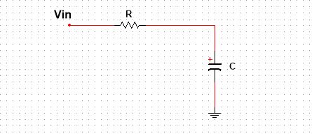
Vin is the input voltage, which can be AC or DC depends on the application. On the application of DC, the capacitor charges. On removal of the DC source, the capacitor tries to discharge itself through the resistor. This charged capacitor can be used for instant discharge through other devicesattached in parallel to it, expect the resistor that is making the whole RC circuit. This property makes this circuit ideal for photoflash and automobile ignition circuits, where you need high instant current.
On the application of the AC signal, this RC series circuit acts as a filter. Meaning, it allows certain frequencies and blocks the other ones, making it a right circuit for communication purposes.
In the rest of the post, I give more info on what happens when you apply a series RC circuit a DC (complete response), or AC signal (frequency response), or just leave it sourceless (Natural response).
The Natural Response
The natural response of a circuit means its behavior in the absence of any voltage or current source. In the case of the RC series circuit, the natural response is very clear. The capacitor will discharge itself through the resistor if the circuit is closed.
The circuit is given below:
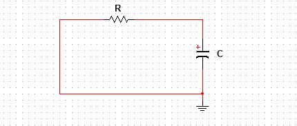
This circuit is best used when attached to other circuitry, photoflash or car ignition circuit, which needs instant current. The instant current means the fast exponential decaying current. Now, I think let’s have a look at some mathematics involved in this circuit, and try to prove it that the current is actually decaying exponentially.
Applying KCL:

This is the first order differential equation. The order of the differential equation depends on the number of capacitors or storing devices in the circuit.
Upon solving this differential equation we would have the following results:

Where,
Vo is the initial charge capacitor voltage.
In the natural response, the voltage and current both decay exponentially. An important point to be noted is the term t, the time constant. The value of a time constant determines the discharge decay rate of a capacitor. The higher the time constant, the higher the decay rate, and vise versa.
Now, let’s see the whole picture of the series RC circuit. In natural response, we assume that the capacitor is initially charged. But from where the capacitor get charged. And if you use this circuit in photoflash, we have to recharge the capacitor again and again. So, how do we will tackle these problems? In the next section, I try to answer these questions.
The Complete Response
The complete response of any circuit is a combination of its natural, transient and steady-state responses. The transient response is the behavior of the circuit before it reaches the steady state, while steady state response can be understood as our end goal behavior for which dwe esign our circuit. No more changes occur when a circuit reaches its steady state.
A complete series RC circuit with a power source is given below, let try to understand it complete response using my favorite simulation software, the Multisim.
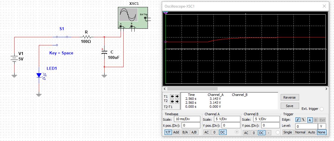
This circuit can be taken as a basic understanding for photo flash, delay circuit. Focus on oscilloscope graph, initially the capacitor has Vo equals to 3.15V, then as the switch turns On there occurs the transient response and the capacitor charges exponentially. After the transient response, the circuit gains a steady state of 5V and remains at the 5V, this is called the steady state response.
When the switch (S1), turn to the LED terminal. The LED turns On for a short time and then turns off. This is the really cool circuit you can try. Play with the time constant and enjoy different delay timings.
Up till now, we study the RC circuit behavior upon application of the DC signal. Now, let see how it behaves when you apply an AC signal to it. In the rest of the post, I will give more info on its frequency response and try to design a passive low pass filter.
The Frequency Response
The frequency response of a circuit tells us the behavior of a circuit with respect to frequency. How a circuit behaves upon application of a certain range of frequencies. As I said, upon application of the AC signal, the series RC circuit acts as a filter. The nature of the filter, low pass or high pass, depends on where you take the output from the circuit. When the output is taken across a capacitor, this makes a low pass filter.
Following is the circuit diagram for low pass filter:
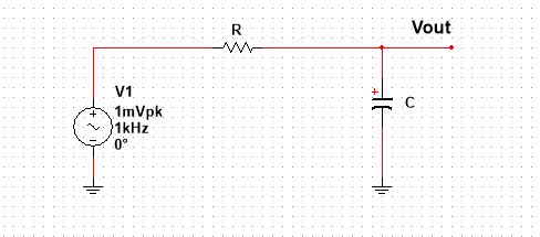
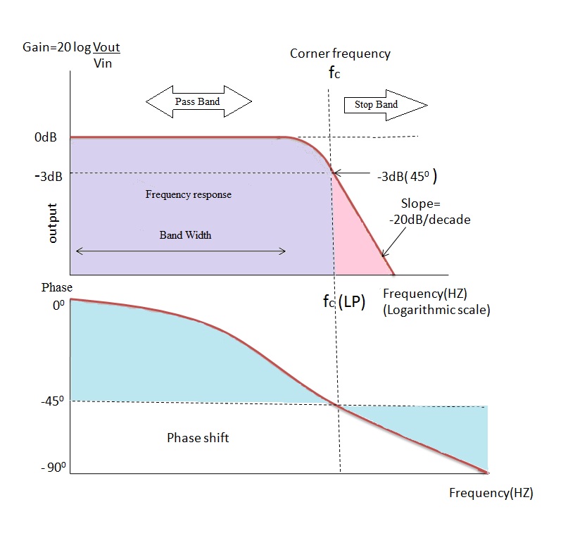
The input AC signal in 1mVpk, but it can be any signal such as communication signals. Following is the diagram of the frequency response, in dB scale, of the series RC circuit acting as low pass filter. (Credit: Electronic hub)The circuit is allowing low frequencies and blocking the other. Fc is the cutoff frequency, a key parameter for designing the circuit. After this cutoff frequency, the amplitude of the signal starts to roll up.
Series RC Circuit Design, A Low Pass Filter
This is my favorite section to talk about. Designing a series RC circuit means what should be the value of R and C for the required application. But if you are using it as a filter, then the design means, what should be its cutoff frequency.
A typical low pass filter is shown in the above figure. The values of R and C will determine its cut off frequency. The frequency and R and C are related by the following equation.

Select the frequency for which you want to design a circuit, then second suppose a standard value of a capacitor, and lastly solve for the value of a resistor. Congrats, you have designed a very basic low pass filter. This is not a good design, but this is where you start designing a low pass filter.
Let’s have a design example. We want a low pass filter for a cut off frequency of 1kHz.
Step 1, choose a standard capacitor value i.e.47nF.
Step 2, solve for the value of the resistor.

The close standard value is 3.3kOhm. And with this, the filter is designed. Let verify it in Multisim software. Following is the AC response, given by Multisim.
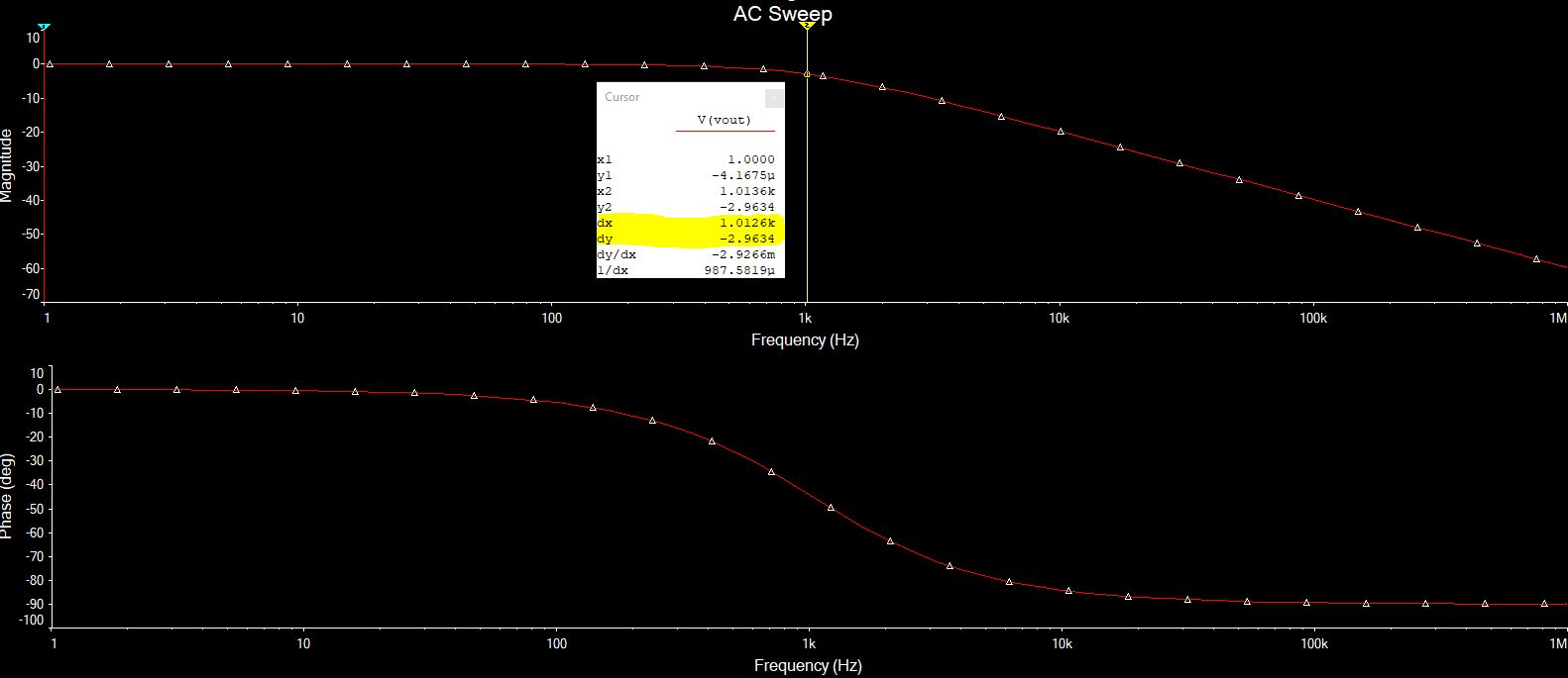
One thing to know, at the cut off frequency, the amplitude of the signal is decreased to -3dB.
Final Words
This is all I want to share about the RC series circuit and the design of passive low pass filter. I encourage you to design your low pass filter using any simulation software you have excess to. Hopefully, this post has helped you in some way.
Thank you and have a good time.
Other useful posts