

Design 5V DC Power Supply (Step By Step Guide 2026)
Hey there! I hope you are doing great. You landed here because you are looking for some help to design a 5V power supply on your own.
Well then, I welcome you here. In this article, we will just not design a power supply but also get to know about design calculations and all the steps involved.
The goal of this article, a guided project, is to share my knowledge with you people so that you became capable of designing your power supply according to your own requirements and specifications.
The power supply which we will design here is a linear technology-based design.
I will go through you each design step, try to present everything in simple language, and will carry out some design mathematics along the way i.e. if a capacitor is being used in the schematic, you should know why it is there, and how its value is calculated.
In the end, we will have a power supply with (just for giving you a rough idea):
- Fixed 5V (DC) output voltage
- Output Current (DC): 250mA
- Ripple factor: up to 3%
- Input voltage (RMS): 220V (AC)
- Features of over current and voltage protection.
- With reverse bias protection.
- Load and line regulations are in the range of 3%.
Hopefully, you will enjoy this post and will learn something.
The design of 5V DC power supply
A power supply circuit is a very basic circuit in learning electronics. Almost everyone in their electronics learning journey tries to make it.
And I can not tell you how much fun it is when you finish your first power supply design, test it, and it works fine.
Alright!
The design of any circuit begins with a well-made general block diagram. It helps us to design the sections of the circuit individually and then at the end put them together to have a complete circuit, ready for use.
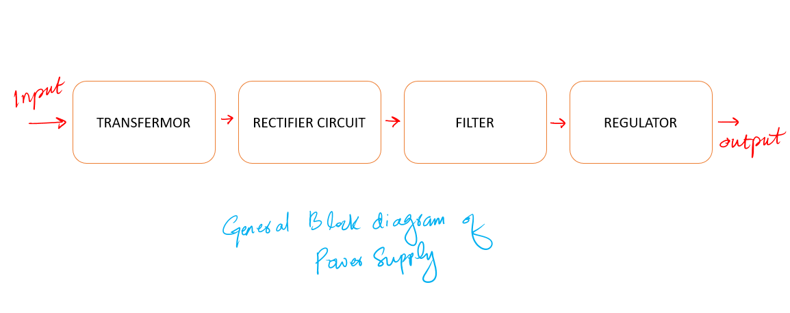
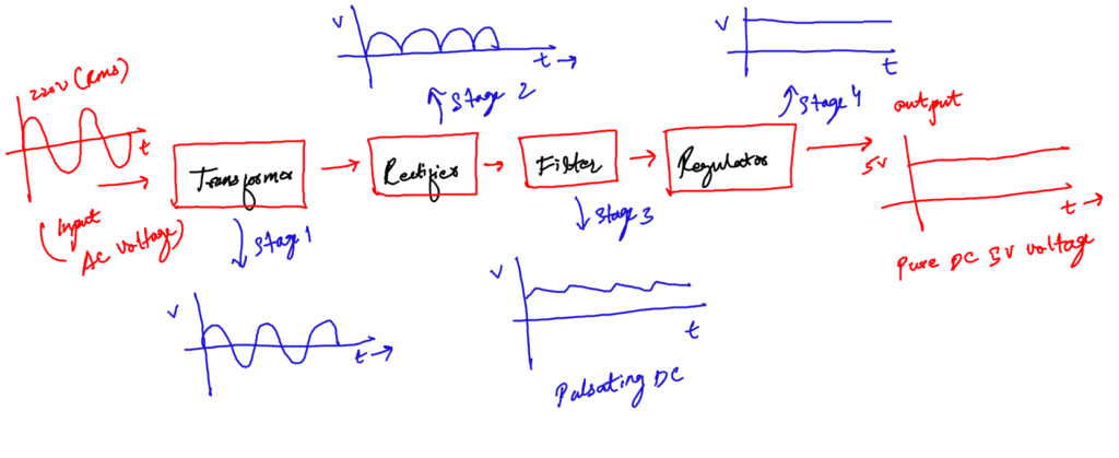
General Block diagram of a power supply
The general block diagram for this project is given below. It is very simple. It has the following four main sub-blocks.
- The Transformer
- The Rectifier Circuit
- The Filter
- The Regulator
First, I will explain each block in general and then we will go for designing. I think you need to understand which block is doing what first.
So, let’s try to understand each section one by one.
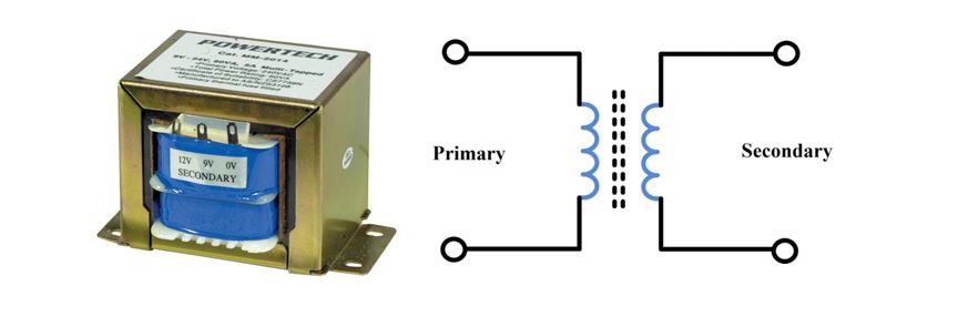
a. The input transformer
A transformer is a device that can step up or step down voltage levels, following the law of conversation of energy.
The question is, why do we need it in our supply design?
Well, depending on your country, AC coming to your home has a voltage level of 220/120 V(RMS).
We need the input transformer to step down the incoming AC to our required lower level i.e., close to 5V (DC).
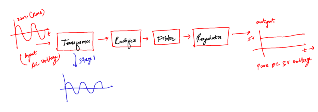
This lower level is further used by other blocks to get the required 5V DC.
A transformer is a device that is used to step up or step down the AC voltages level, keeping the input and out power the same.
Be careful when playing with this device.
As you are using the main supply voltage which can be too dangerous. Never touch any of the terminals with bare hands or with bad instruments.
Have a good and decent non-contact voltage tester like the NCVT3P, and use it to always be sure of which line is the live wire coming to the transformer.
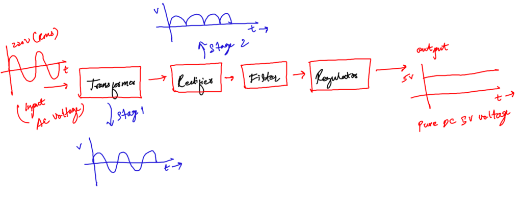
b. The rectifier circuit
If you are thinking the transformer just stepped down the voltage to 5V DC. I am sorry, you are wrong like once I was.
The stepped-down voltage is still AC. To convert it into DC, you need a good rectifier circuit.
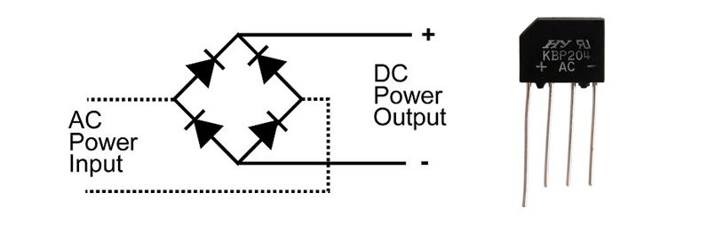
A rectifier circuit is the combination of diodes arranged in such a manner that converts AC into DC voltage levels.
Without the rectifier circuit, it is not possible to have the required output of 5V DC voltage.
This circuit comes in nice integrated packages, or you can make it using four diodes as well. You will see how we design it in later sections.
Basically, there are two types of rectifier circuits; half-wave and full-wave. However, the one which we are interested in is a full rectifier, as it is more power-efficient than the first one.
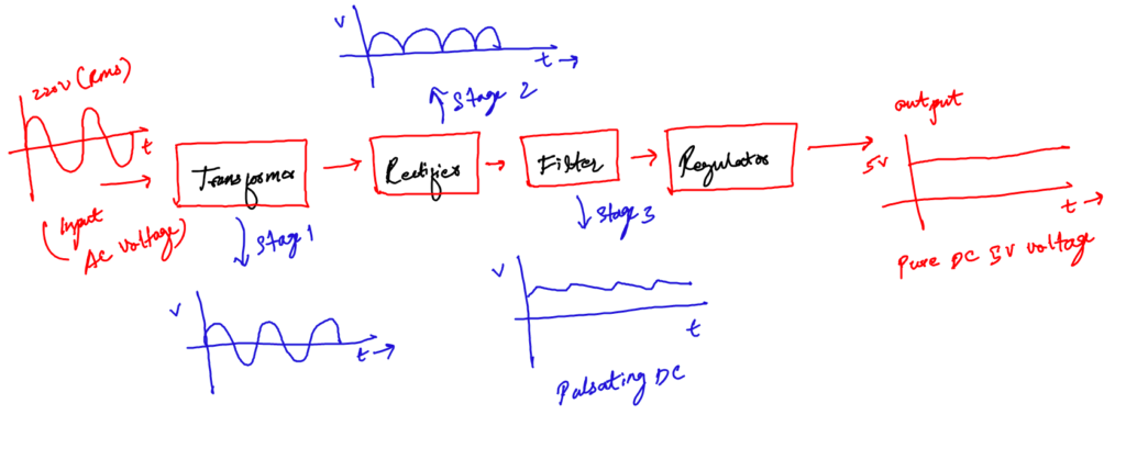
c. The filter
Nothing is ideal in practical electronics. The rectifier circuit converts the incoming AC to DC but unluckily it does not make it a pure DC. The output of the rectifier is pulsating and is called pulsating DC.
This pulsating DC is not considered good to power up sensitive devices.
So, the rectified DC is not very clean and has ripples. It is the job of the filter to filter out these ripples and to make the voltage compatible for regulation.
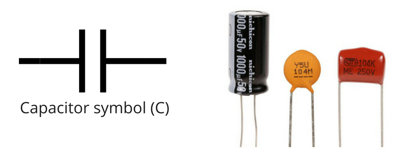
A capacitor filter is used when we need to convert a pulsating DC into pure or to remove distortion from signal
A rule of thumb is DC voltage must have less than 10 percent ripples to be regulated perfectly.
The best filter in our case is the capacitor. You may have heard, that a capacitor is a charge storing device. But actually, it can be best used as a filter. It is the most inexpensive filter for our basic 5V power supply design.
d. The regulator
A regulator is the linear integrated circuit used to provide a regulated constant output voltage.
Voltage regulation is very important because we do not need a change in output voltage when the load changes.
An output voltage independent of the load is always required. The Regulator IC not just makes the output voltage independent of varying loads, but also from line voltage changes.
A regulator is the integrated circuit used to give a constant output voltage regardless of input voltage changes.
I hope you have developed some basic concepts of power supply design. let’s go further with the actual circuit diagram for our specific 5V DC power supply design.
Circuit diagram of 5V DC power supply
Below is the circuit diagram for the said project. You get the main supply; voltage and frequency can depend on your country, fuse; to protect the circuit, transformer, rectifier, capacitor filter, an LED indicator, and the regulator IC.
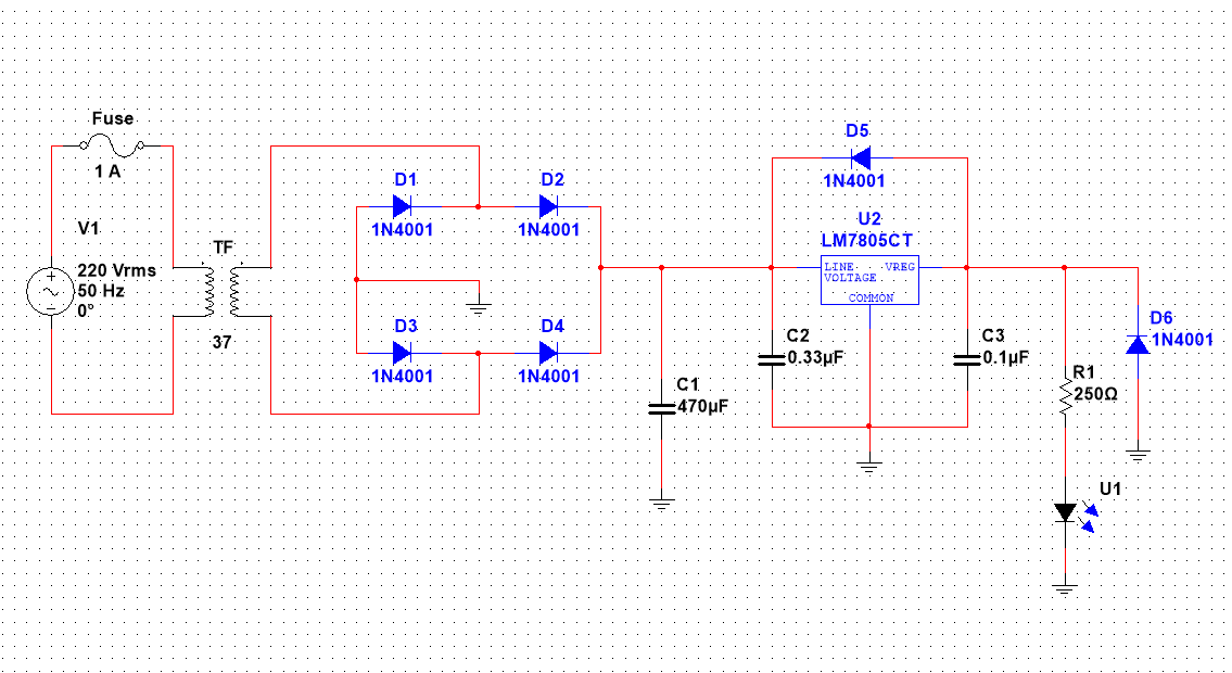
The block diagram is implemented in NI Multisim software, good simulation software for students and electronics beginners. I encourage spending some time playing with it.
Now, let’s get into the actual design.
Step by step method to design 5V DC power supply
Here is the deal, we will design each section first, and then put together each of them to have our DC power supply ready to power up our projects.
So let’s get started step by step.
You are thinking, that I would start the design explanation from the transformer but it is not the case. A transformer is not selected at the very first.
Step 1: The selection of regulator IC
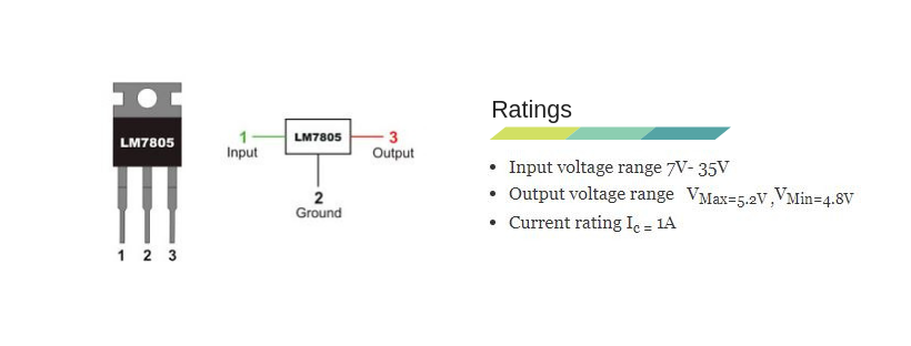
The selection of a regulator IC depends on your output voltage. In our case, we are designing for the 5V output voltage, we will select the LM7805 linear regulator IC.
In the design process, the next thing is, that we need to know the voltage, current, and power ratings of the selected regulator IC. This is done by using the datasheet of the regulator IC.
The following are the datasheet provided ratings and pin diagram for LM7805.
The datasheet of 7805 also prescribes to use of a 0.1μF capacitor at the output side to avoid transient changes in the voltages due to changes in load.
And a 0.33μF at the input side of the regulator to avoid ripples if the filtering is far away from the regulator.
Just for extra knowledge, for positive voltage output, we use LM78XX. XX indicates the value of output voltage and 78 indicates positive output.
For negative voltage output use LM79XX, 79 indicates negative voltage and XX indicates the value of output.
Step 2: The selection of transformer
The right transformer selection means saving a lot of money. We got to know, that the minimum input to our selected regulator IC is 7V (See above datasheet values).
So, we need a transformer to step down the main AC to at least this value.
But, between the regulator and the secondary side of the transformer, there is a diode bridge rectifier too.
The rectifier has its own voltage drop across it i.e., 1.4V. We need to compensate for this value as well.
So mathematically:
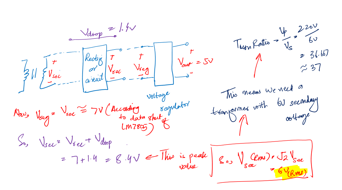
This means we should select the transformer with a secondary voltage value equal to 6V (RMS) or at least 10% more than 6V (RMS).
From these points, for the 5V DC power supply design, we can select a transformer of current rating 1A and a secondary voltage of 6V (RMS).
Why is 1A current? Because the regulator IC has a current rating of 1A, meaning we cannot pass more current than this value.
Selecting a transformer with a current rating of more than this will cost extra money. And we don’t need it.
Step 3: The selection of diodes for the bridge
You see in the circuit diagram, the rectifier circuit is made by arranging diodes in some patterns. To make a rectifier we need to select the proper diodes for it.
When selecting a diode for the bridge circuit. Keep in mind the output load current, and maximum secondary voltage of the transformer i-e 6V(RMS) in our case.
Instead of individual diodes, you can also use one individual bridge that comes in an IC package. But I don’t want you to use it here, just for the purpose of learning and playing with individual diodes.
The selected diode must have the current rating more than the load current (i.e. in this case is 250mA). And peak reverse voltage (PIV) more than peak secondary transformer voltage.
We select the IN4001 diode because it has a current rating of 1A more than our desired rating, and a peak reverse voltage of 50V.
Peak reverse voltage is the voltage a diode can sustain when it is reverse biased.
Step 4: The Selection of smoothing capacitor and calculations
Things we need to keep in mind while selecting a proper capacitor filter are, its voltage, power rating, and capacitance value.
The voltage rating is calculated from the secondary voltage of a transformer.
The rule of thumb is, that the capacitor voltage rating must be at least 20% more than the secondary voltage.
So, if the secondary voltage is 8.4 V (Peak value for 6V (RMS)), then your capacitor voltage rating must be at least 50V.
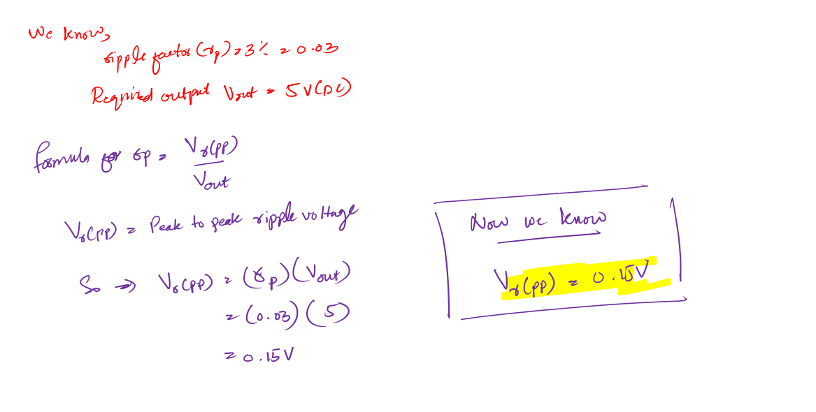
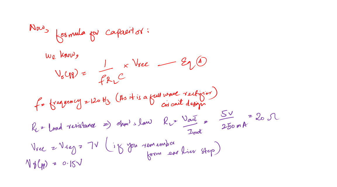
Second, we need to calculate the proper capacitance value. It depends upon the output voltage and the ripple factor (the effectiveness measure of the capacitor filter).
If you remember I shared, in the beginning, that we want to design a 5v power supply for at least a 3% ripple factor.
Calculations for capacitor value in power supply design:
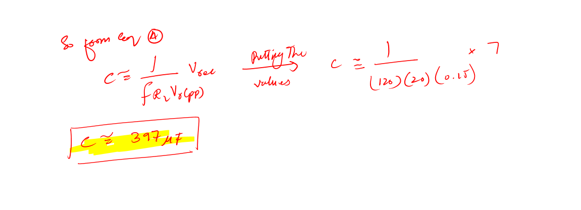
Now, this value of the capacitor is not a standard one. Remember in most of your designs you will not have a standard value all the time.
A good practice is always to choose the close one to your theoretical value.
I use this online calculator, Standard value solver, which helps me to choose the nearest standard value to my theoretical values. And for this above value, the nearest value is 470uF.
So, the capacitor which we gonna use for our design is 470uF
Step 5: Making the power supply safe
Every design must have a safety feature to protect it from burning. Similarly, our simple supply must have one i.e. the input fuse. The input fuse will protect our supply in case of overloading.
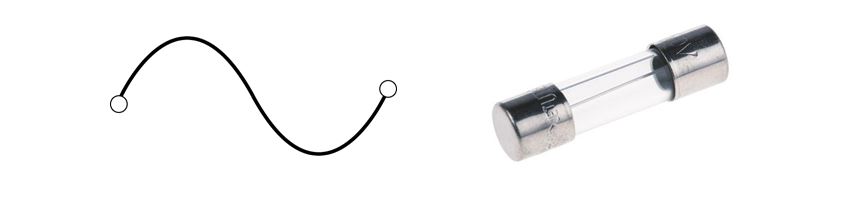
For example, our desired load can handle 500mA. If in case our load starts to miss behave, there is a chance of burring of components. The fuse will protect our supply.
A rule of thumb for selecting the fuse rating is, it must be at least 20% more than the load current.
The simple power supply we designed has the capability to deliver 1A current, which in some cases you can use it for.
If you decide to use it for such cases, then don’t forget to attach a heat sink to the regulator IC.
Conclusion
If you are an electronics hobbyist or beginner, I would recommend you design your own lab power supply.
It will help you learn electronics as well as give you the best lab power supply.
Please do not specify the above power supply we designed it to just be a 250mA supply. It can be your 5V DC power supply in general with up to 250mA current capability.
This means you can use it for the current range of 0 – 250mA. Far from this range, the power supply will degrade its performance as it is only designed for this range.
If you decide to make the above power supply on a breadboard. Make sure you test the components with a component tester like the m328 tester before you put them in the circuit.
And guys, this is it. It was what I know how to design a 5v DC power supply. Hopefully, it was some kind of help to you.
Now it is your turn. Please share in the comment which stage of designing a power supply you like. Also, if you have any questions let me know.
Share it in your circle, it will help me a lot.
Thank you and have a good life.
Other useful posts
Wow this was helpful for me
HI thanks for this, but I have a lil problem and and I don’t understand. I’m to design and simulate Dc regulated power supply to produce 5Vdc for music system, and music may consume 500mA current design parameter and rippe voltage peak to peak should not exceed 1% of Dc value. Can u pls help me?
Ooh sir am a technician from uganda you gave taught me well about 5v dc power s design
Thank you for the useful post!
For some reason in step 4 I am not getting the final capacitor value even when I am substituting the same values you have used.
Instead of getting 397uF, I am getting 0.0194F, where did I go wrong?
Thank you
hi, can I use a 12v transformer for this ..
Thank you for your walkthrough, this was well put together.
I think there might be a slight mistake in your calculation for the filtering cap though.
You calculate that the load resistance is 20 Ohms and that the current draw is 250mA. But maybe these numbers were mixed up?
In your schematic R1 has a value of 250 Ohms. That means the current draw is going to be (5V-2V)/250 Ohms = 12 mA. where I’m assuming there’s a ~2V drop across the LED.
So if we assume a ~15mA draw, then the filtering cap would need to be:
15mA / (120Hz * .15V) = 833 uF
If we assume instead that the load IS only 20 ohms. Then the current draw will be ~ 10x that, and the cap will have to be 10x larger. i.e. 8,330 mF.
Maybe I misunderstand something?
If I run just your numbers though
7V / (120Hz * 20 Ohms * .15 V)
I get the value 19.4 mF, so I don’t think the 470 uF is the correct cap size.
can you please tell me what to do to get 1A current at output along with 5V.
Good PM.
Sir Abbas,
Thank You for this article, It helps me a lot to complete my class project in Electronics. Again Thanks and God Bless.
Regards,
Sir Lita
what does diode d5 and d6 do?
Hi.
Thank you for the article but i can’t find the capacitor value you calculate. Is your formulae ok?
Thank you.
It was helpful . Thanks alot
Welcome 💕
THANKS AND BE BLESSED
Welcome and you too 💕
Hello. Thanks a lot for the post, it’s very helpful. I just can seem to find the same value of capacitance of 397 uF as you did in my calculations. Am I missing something?
Welcome and sure let me see your calculations
Thank you very much. It was really helpful. It’ll help me complete my project.
Welcome 💕
you wrote: The rule of thumb is, the capacitor voltage rating must be at least 20% more than the secondary voltage. So, if the secondary voltage is 8.4 V (Peak value for 6V (RMS)), then your capacitor voltage rating must be at least 50V.
How do you get 50 from 1.2*8.4?
I followed everything else, but this confused me.
Hi Les,
least 20% means that it should not be less than this and can be high as easily available to you from the market. 25V can be used as well here but because the supply is intended for beginner so to make it on safe side as possible 50V is used.
This is a super great article. I would be very interested in the full video package for power supply design. It would help a lot in my EEE final year project. Cheers!
Thank you 💕
Hi Abbas. Please May I know why a 1 kilo-ohm resistor is connected in series with an LED in the circuit diagram above ?
Hi there, this is a current limiter resistor. It is limiting the current flow to the led to prevent it form damaging.
Hi. Can you please explain what you mean towards the end when you say – “Please do not specify it to just a 500mA supply. It can be your 5V DC power supply in general with up to 500mA current capability”
Hi, I meant that you can use it to draw up to 500mA.
You know, if a power supply says 500mA (it can be any other value) some students think that it is specific to just 500mA. What they don’t understand or miss out on, in my opinion, is that the current from the power supply depends on what load you are attaching to it.
practical DC power supply that can be used as the power supply for 100-ohm load
Thanks a lot, can you do the with 30v variable supply with find coarse adjustment?
can you give me an example of Dc power supply circuit that has 5 diodes and a voltage selector.
I think the example would be power supply with wheeling diode feedbacking the output into the voltage regulator input. We use such diode for protection purpose.
can you do it? design a simple circuit that is similar to the example that i gave. just replace the diode to an output of 5 different voltages
Mark, a while ago I wrote a description for a power supply DIY (Click here to know more .. ). I think that description has a circuit diagram that can be very helpful to you. It has diodes at the output.
I’ve a damaged power supply circuit which I want to repair but I don’t know about a resister component which is burnt and the color codes are hard to read . Can you help if I send you pics of the PCB?
Thank you so much for this Engr. Yaman! 🙂
What a neat and clean explanation
Very well explained
🙂
Thank you for this article. helped me very much
You are very welcome 🙂
Thanks a lot for yaman…
Welcome 🙂
It’s a helpful article 😊.. Thanks
Welcome 🙂
Actually it is very educative thank
You are very welcome 🙂
Thanks very much because it helps me to complete my project.
You are welcome 🙂
Hi pls i need the designning board of,A simple 5V DC regulated power supply system.
Please would you give me.
Thanks a lot, this would help with my assignment.
Welcome 🙂
intresting indeed its a gd leaning project
Yeah it is 🙂
Thank you
We are progressing well.