

Hi. I hope you are having a good time. In this post, I am going to share my knowledge on how to design a half wave rectifier circuit. The rectifier circuit is single phase and uncontrolled i.e its diode based.
I am not going in the total theory, I will share how to design it, how to see the input and output waveform in terms of Fourier theorem, how to calculate your load, how to select the right diode, what is the actual meaning of rectifier efficiency. In summary, a lot of fun stuff to explore.
Hopefully, you will enjoy it and will make it to the end.
The Half Wave Rectifier Circuit
A lot of people think the rectifier circuit converts AC into DC, which is correct. But I personally believe, it is more likely to convert any multi directional signal into unidirectional.
For example, in the case of AC into DC, AC is two directional i.e it has a positive peak as well as negative peak, the rectifier eliminates the positive or negative portion making it a unidirectional signal called the pulsating DC (positive or negative).
So, in general, we can go with my stated definition. And please don’t limit AC to just a sinusoidal waveform, it can be triangular or square depending upon the application.
Now, let see how the circuit of half wave rectifier looks like and try to learn more about it.
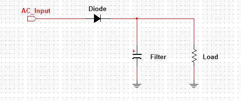
You see, it is a very simple circuit. It has a diode, a capacitor acting as a filter, and a resistor representing your load. Ignoring the filter we have left with two configurations of the diode, either we can have diode anode terminal connected to AC input or with the load. In the first case, we would have a negative peak blocked while in the later we would have a positive peak blocked.
In the above image, I go with diode anode connected to AC source and get the negative portion blocked. And when you flip the diode the output gets inverted. It is very cool to try it yourself. By the way, I am using Multisim Student Edition for this post. I like Multisim, but you can try it in any simulation software.
The Half Wave Rectifier Circuit Design
Designing a circuit not just means you have to know how to calculate the values of each component. The design begins when you get the confidence that this circuit, you gonna design, is the right option for the present application. In summary, among many other questions, you need to answer how efficient the design is for my current application?
Talking about efficiency, you can clearly see it must be below 50% as half a negative portion is blocked. Subtracting the rectifier itself loss half wave rectifier circuit gets the efficiency of 40.6%, which according to me is not very fine.
But the circuit is too simple and cost-effective that a lot of applications make use of this circuit, especially in toys, communication as a peak detector, radios, beard trimmers, and iron solders.
Now, let’s get into its design. It is a very simple circuit and fun to design. Wait, I think I can add something more here. You see the output voltage is unidirectional but you can’t say what value DC it is. A DC is usually a constant value, which is not true in our case. To solve this issue we will go with the average DC value.
Focus on the following image (Source: electrical4u)
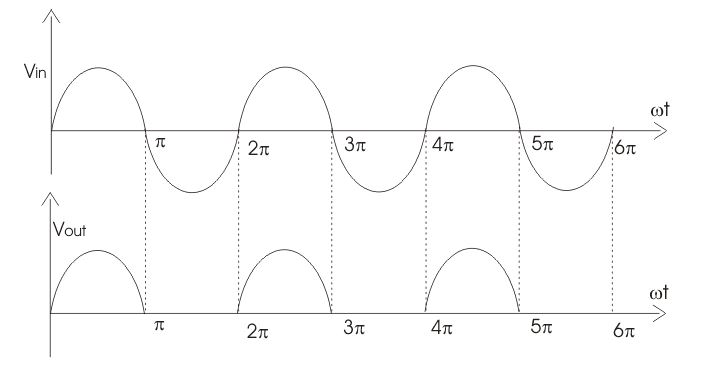
To calculate the average DC value we will use Fourier Series. Forget about the cos and sin terms just focused on its DC term. The output voltage is the sin wave with the time period of 2Pi. With this information let solve it with Fourier Series.
dt%20)
dwt%20)

Last equation shows the average output voltage. Vo is the peak voltage of input AC voltage to the diode. The integral value is set from 0 to Pi, it is because form Pi to 2Pi period the signal is zero, which means no need to calculate it.
Similarly, the output current is in phase with voltage and can be calculated by divide the output voltage by the load resistance.

We have output DC power and input AC power, why not to calculate its efficiency. The efficiency of the rectifier is the ration of output DC power to input AC power.


I think I have shared what I know about the topic, let’s get into the step to actually design a half wave rectifier.
Step 1: Calculating the Load
The first and most important thing is to estimate your load i.e for which type of load you are to design the half wave rectifier. This can be done as follows.
- Using Ohm’s Law, you know which operating voltage and current your device has, calculate the resistance value. This resistance value is your estimated voltage.
- If you are given the power in wattage and voltage, then by using the following power equation you can calculate the required resistance value.

- If you are given the power in wattage and current, then by using the following power equation you can calculate the required resistance value.

Sometimes, if it is not possible to theoretically calculate your load, a rough but educational guess can also be helpful. But this is a very rare case Ohm’s Law will almost work in every situation.
Step 2: Selecting The Right Diode
Usually, people limit a half wave rectifier circuit to just a linear power supply application, which is not a good idea. In the said power supply, you have a frequency less than 100 Hz but in switch mode power supply you use the same circuit but this time you are dealing with frequency in kiloHertz.
The point I want to clear is that the frequency handling must be the first thing you would look for when selecting the right diode for your circuit.
The next thing is the power handling capability. Always be sure you select the diode compatible with the required power ratings.
Let me tell you something interesting here, a diode will always have a specific voltage drop across it i.e in case of silicon diode it is 0.7V. So, look for the current in the datasheet and compare it with your load current. This current should be at least 20% more than the load current.
Next is the peak reverse voltage, the PIV ratings. You know voltage drop is not the issue when a diode is forward bias, the current is. But in reverse bias reverse voltage does matter.
The best practice is, the datasheet provided value of a diode peak reverse voltage must at least 20% more than the expect reverse voltage in the circuit across it.
Step 3: The Output Capacitor Filter
Form the Pi to the 2Pi period there is no output voltage, which is equal to turning off the connected device with it. Sometimes it is good but it is not always required. The situation where it is not suited is, of course, the power supply. To fill up this gap a capacitor is introduced.
The value of the capacitor should not be much higher or much smaller, it must be the intermediate value. Large value results in slow charging and discharging and vise versa for small value.
The voltage rating must be at least 20% more than the peak output voltage.
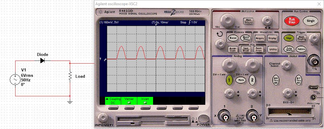
Step 4: Testing The Design Circuit
When you have done the design process, it is time to test your circuit. This can be done with a multimeter or oscilloscope. I will go with the oscilloscopes because it gives you an in-depth analysis. You can confirm your result with a multimeter but for fault analysis, you have to go with an oscilloscope.
Now, you have theoretically calculated the average DC value, connect the multimeter across the output terminals of the circuit. See if the multimeter is giving the exact value with 1 to 5 % tolerance, you just did a great design, congrats.
If the tolerance is more than the said one, try to optimize the value of the capacitor or maybe you have done other things wrongs. And let me tell, you will make mistakes but it is very fine. I made a lot of mistakes myself too along the way. So, mistakes are the part of learning, enjoy it, learn from it.
Design Example of Half Wave Rectifier Circuit
We are given a load of wattage 0.2W and voltage rating 5V. The problem statement is, we need to design a half wave rectifier to power the device up from the main power AC i.e 220V.
Solution:
Load Calculation
Calculate the load by using the following formula,

it is 125 Ohm which is very low resistance.
Diode Selection
The input AC voltage is 220V @ 50Hz, which needs to be step down to 6V AC using a transformer. The transformer’s secondary voltage is 6Vrms with a peak value of 8.5V. So, the PIV of the required diode must be at least 12V.
We can go with any forward voltage, just need to know the current which will pass through it in its ON state. This current and load current are the same, so from the given load parameters, it is easy to calculate the diode forward current using the following equation.
R is 125Ohm, and power is 0.2W. By doing simple maths we would have the current value of 40mA. Now, we have everything we need for the proper selection of a diode. Next thing is to go any electronics supplier website like Digikey and search for a standard rectifier diode, using the filters you will end with a perfect solution.
Capacitor Filter Calculation
This can be tricky and need to try and fail approach. Sometimes you select a value that works with some loads but fail with other loads or when load parameter changes with temperature or other possible conditions. Try not to chose a very big value because it will be very expensive and also dangerous if you are very new to electronics.
Use the following formula can be very helpful to determine the value of the capacitor.

In our case, Io is 40mA, and Vo is 5V. Using simple maths we would have a capacitor value of 2.547E-5. The close standard value is 0.22uF, so we will go with the said standard value. Always go with the standard values, as almost every manufacturing company makes capacitors of these values, and they are easily available in local electronics shops or online.
Final words on half wave rectifier circuit design
A Rectifier converts AC into DC. There are two types of rectifiers, half wave, and the full wave. The first, the topic of our interests, only allows one portion of the input AC and blocks the other.
In this post, a design procedure is presented using which you would be able to design a half wave rectifier circuit.
When you have done with components calculation. The most challenging part is, almost there exists no such value, i.e you calculated value of capacitor but eventually, it comes out a non-standard value. This happens a lot, so don’t worry, select the component with a close approximation.
Yeah, this is all I have for you about the design of half wave rectifier circuit. I hope you have learned something.
The following are helpful resources to learn more about diodes.
- Easy diode reading for beginners (Pin, Bridge, Zenor)
- Diode Testing (Know if a diode is bad, open, or short)
- Diode Anode Cathode Identification (#2 Easy Methods)
- 13 Diode Functions in Circuit (Key Roles of Diode)
- Bad Diode Symptoms (How to know if a diode is bad)
- Identify terminals of unmarked diodes (Easy Solution)
- How To Test Diode Without Multimeter (Easy Solutions)
- Learn Diode Basics for complete beginners (Easy guide)
Free resources for someone just getting started with electronics.
- 21 Best electronics tools & equipment for beginners
- 15 Best Electronics Component Kits For Beginners
Thank you and have a grateful life.