

Transistor basics: Everything beginners must know 2026
You use a mobile phone, laptop, and other awesome electronics gadgets almost every day. These gadgets become possible by the replacement of large bitch size vacuum tube with a tiny electronic component, the transistor.
A transistor is the basic building block of any portable device available in the market. Electronics is nothing without this components. Transistor is a three terminal semiconductor device with collector, base and emitter terminal used for the amplification of small signals or used as an electronic switch. NPN and PNP are two types of transistor each one with its unique characteristics.
In this article, we are going learn everything about the transistor basics.
What is a transistor?
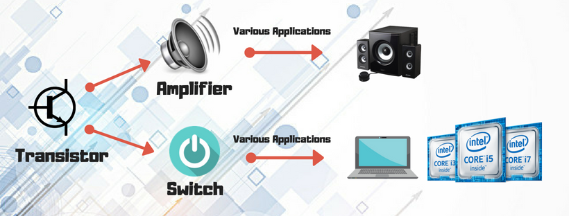
The transistor, is a three terminal semiconductor device used as an amplifier or an electronic switch.
As an amplifier, it amplifies a very week signal into the much larger signal. A simple example is a loudspeaker, which generates a very loud sound.
One loudspeaker can produce a sound which can be heard in the entire hall or stadium.
As switch, obviously it is used for turning a device ON/OFF. This switching ability has made transistor ideal for many applications, like analog to digital converter, switched mode power supply, microprocessors and many more.
Transistor is a three terminal semiconductor device used for the amplification of small signals or used as an electronic switch.
We cannot imagine this modern day electronics without it. Almost every electronic device has a number of these small devices ranging from a few to millions.
You will be shocked if you get to know how many transistors are there inside the circuits of your mobile, laptop, or personal computer! They are in millions.
Importance of transistors in electronics
For understanding the importance and demand of transistor, let’s take an example of a computer.
If transistors were not invented, maybe we would be using bulky vacuum tubes till today.
Our computers would have been made from these bulky size tubes, making computer size as big as a room. Who would have such a big size computer in their houses?
Of course no one except the big companies.
In summary, there would be no personal computer without the transistor. A personal computer is just one example, you can think of radio, mobile, and TV revolution as well.
We would have no such entertainment and modern connected world without these small devices, the transistors.
According to Wikipedia, in 1956 John Bardeen, Walter Houser Brattain, and William Bradford Shockley were honored with the Nobel Prize in Physics “for their researches on semiconductors and their discovery of the transistor effect”.
Twelve people are mentioned as directly involved in the invention of the transistor in the Bell Laboratory.
Symbol of a transistor
Symbol makes it easier to identify a certain element in a complex circuit. Just like other basic electronic component transistor has its symbol. Following is the transistor symbol:
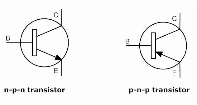
As I said earlier it is a three terminal device. Three terminals are base (B), the emitter (E) and collector (C). Base terminal acts as a gate, controlling the amount of current flow between emitter and collector terminals. It is very important to know the following about a BJT transistor:
- It is called a bipolar junction transistor because it has both holes and electrons as charge carriers.
- It is a current controlled device i-e amount of base current controls the amount of output current.
- The resistance between base and emitter is lower than the resistance between base and collector.
- There are three regions of operation for a transistor i-e Active, saturation and cut off region.
The VI Curve of a transistor
Just like a diode, the transistor has it VI curve (called the characteristic curve). The other important thing you need to know is: what is the relation of the voltage across the device and current flowing through it. This information is given in the transistor datasheet as VI graph.
In case of the transistor, the voltage across the transistor is VCE and current is collector current (IC). But the interesting thing is, base current controls the collector current.
For every base current value, we have different collector current value. In result, instead of a single VI curve (as in the case of the diode) we got a family of VI curves.
Following is VI family curves;
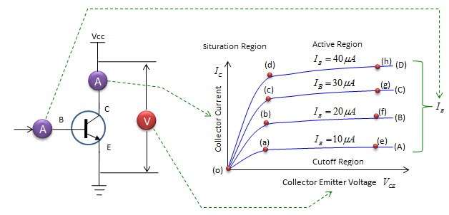
You see, for every base current, you have a different VI curve. The VI curve can be divided into following three explained regions.
Transistor regions of operations
1. Active region
In the active region, the transistor will be ON. Furthermore, in the active region, the base-emitter junction is forward biased and the base-collector junction is reverse biased.
The collector to emitter voltage (VCE) will be in between cut-off and saturation regions.
In VI graph you can clearly see a constant collector current in this region. So, in active region transistors could be used as a constant current source and as the amplifier.
2. Cut-off region
In this region, both the base-emitter and base-collector regions are reversed biased.
The operating conditions of the transistor are: (a) Zero input base current ( IB ), (b) Zero output collector current ( IC ), (c) And maximum collector voltage ( VCE ) which results in a large depletion layer and no current flowing through the device.
This region is mainly used in switching conditions.
3. Saturation region
When both the base-emitter and base-collector regions are forward biased, the transistor is said to be in the saturation region.
In this region, the transistor is used as a resistor or as an active load in integrated circuits.
Transistor physical appearance
We understood the basic definition of a transistor. It is time to see real transistors. Following is the picture of real transistors:
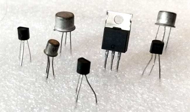
You see, all of them are of different shapes and sizes. Some are covered with white materials, actually, this white material is a heat sink. These are solo ones i-e they are not used in the circuit yet.
The NPN and PNP Transistor
Bipolar junction transistors come in two types one is called the NPN and the other is called PNP. Both types perform the same operations but different in the following ways:
- A PNP transistor is made up of two P-type material layers with a layer of sandwiched of N-type. Where the NPN transistor is made up of two N-type material layers with a layer of sandwiched of P-type.
- In PNP transistor, the majority charge carriers are holes, wherein NPN the majority charge carriers are electrons.
- A PNP transistor turns ON by applying some negative voltage or no voltage. While NPN transistor turns ON when there is some voltage at the base and some current is flowing into the base terminal.
- In PNP transistor, the flow of current runs from the emitter terminal to the collector terminal, wherein NPN the flow of current runs from the collector terminal to the emitter terminal.
I am personally more interested in the design of electronic circuits.
So, from a design point of view, it is very important to know how to identify which transistor is which. As a designer, it is your job to practically differentiate between NPN and PNP transistor.
As I told you earlier, PNP transistor needs negative or no voltage at its base and NPN needs a positive voltage at the base terminal.
Check out our detail article on NPN and PNP transistor.
Transistor terminal identification
We learned how to differentiate between NPN and PNP.
The next thing in learning transistor basics, is how to identify the terminals of a transistor. Identification of right terminals is very important, because if you attach a power source to wrong terminals of a transistor, it may burn out.
I have two methods to share with you.
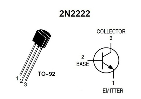
First method: By using the datasheet
From the datasheet, you can tell which terminal is which. In the datasheet, you will always be given a picture like below.
Just compare your actual transistor with it by holding the transistor the way shown in the datasheet.
I personally, used to apply this method when I was a student.
It was so simple like I did not have to borrow a multimeter from university lab or use my own later on when bought one.
I just Google the transistor, download the datasheet. And compare the transistor in my hand with the picture in a datasheet.
This just worked fine for me but later on, I enjoyed doing it by using a multimeter.
Second method: By using multimeter
To be honest there are many many you can identify a transistor terminal by a multimeter.
But personally, I am comfortable with the following one. Keep in mind that the mid-terminal of a transistor is always base so do not waste time finding the base terminal.
Key points to be noted to identify terminals of a transistor
- Set the multimeter in diode mode.
- Remember base-emitter resistance is low than base-collector resistance.
- Place the positive probe (red) of the multimeter on the base of the transistor (NPN). But if your transistor is PNP then put a negative (black) multimeter probe on base.
- Place the other multimeter probe on the other terminal of the transistor, and note the values of resistance.
- Low resistance is the emitter terminal.
- High resistance is collector terminal.
Transistor testing
Transistor testing is the most important point to learn for transistor basics. Because it is very important to differentiate between a good and bad transistor.
You got a transistor and want to know if it is working fine or not. Or you just fulled out a transistor from other circuit board and want to check if it is still working fine.
You need to test it.
There are several ways you can do it. But what best for a beginner is do it by using a multimeter. You can use any multimeter, it does not have to expensive, as long as it check continuity test.
- Set the multimeter to continuity check point.
- Touch the probes together, if multimeter beeps, it means your multimeter is fine. You can test transistor with it.
- Next, place the probes of the multimeter on the terminals of the transistor under test and listen to the beep.
- If multimeter beeps for any arrangement, it means you got a bad transistor.
If you want to learn more about transistor testing check out our article:
The Transistor as an amplifier
Many times we deal we weak signal in nature. Like our voice can be heard within limited space.
It can not be heard when we are speaking in public. There is always a need of third party application to increase our voice enough to be heard in big crowed, the loud speakers.
Loud speaker do it using amplification process. In the amplification process, the strength of a weak signal is increased without altering its characteristics.
Input signal can be anything, current or voltage, transistor as an amplifier will amplify the signal without altering its unique characteristics.
If we want a transistor to work as an amplifier we should make the transistor to work in the active region which lies between the saturation and cutoff region.
To make a transistor work in the active region, we need a specific circuit configuration. Following are the main three such circuit configurations.
- Common Base configuration (CB): in the CB configuration we will connect the base of the transistor to ground, which has a very low input impedance which will give very low output impedance with very low amplification. The gain for this configuration will be very low.
- Common Collector configuration (CC): in this configuration collector is connected to ground, we have low output impedance for high input impedance and gain for this configuration is very good when compared to CB configuration.
- Common Emitter configuration (CE): in this configuration emitter is connected to ground and we will have input impedance will be high, the output impedance will be medium and gain will be high.
Transistor amplifier parameter
We need to consider the following specifications before choosing the transistor amplifier. The specifications are input impedance, efficiency, bandwidth, gain, slew rate, linearity, stability, etc.
- Input impedance: It should be 10 times higher than the source impedance for good amplification.
- Efficiency: The efficiency is nothing but how much input power is effectively used to get the output of the amplifier. In other words, efficiency is nothing but how much power is drawn from the power source and how much power is efficiently used to get output by the amplifier.
- Bandwidth: The frequency range where amplifier can do a good amplification of the signal is called bandwidth of that amplifier.
- Gain: The gain of the amplifier is measured by calculating the ratio between the output power to the input power. Higher gain circuits will be highly sensitive and give good output even when the small input is given.
- Stability: The ability of the amplifier to avoid self-oscillations. Because of these oscillations, the signal might be overlapped or get masked by the useful signal. Stability can be reached by adding a zonal network at the output which will produce negative feedback.
- Linearity: If the input of the amplifier is increased the output of the amplifier should also increase linearly this effect is called linearity. This effect will be 100% achieved by the ideal amplifier, when we take the practical case the amplifier will produce linear output for its input up to a certain limit, after that if input frequency is increased the output gain will be decreased due to the internal parasitic capacitance of the signal. This nonlinearity can be reduced by negative feedback.
- Noise: Noise is defined as the unwanted frequencies in the signal due to the component interface, external interference, component failures, same frequency signals in the same circuit, etc.
The Transistor as a switch:
In a transistor, no current can flow in the collector circuit unless a current flows in the base circuit. This property allows a transistor to be used as a switch.
A transistor operates as a “single-pole single-throw” (SPST) solid state switch. With a zero signal applied to the Base of the transistor, it turns “OFF” acting like an open switch and zero collector current flows.
With a positive signal applied to the Base of the transistor, it turns “ON” acting like a closed switch and maximum circuit current flows through the device.
The simplest way to switch moderate to high amounts of power is to use the transistor with an open-collector output and the transistors Emitter terminal connected directly to ground. When used in this way, the transistors open collector output can thus “sink” an externally supplied voltage to ground thereby controlling any connected load.
Types of Transistor
Besides BJT type transistors, there are many more. Following diagram summarizes the whole concept.
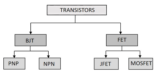
The transistors classification can be understood by observing the above tree diagram. Transistors are basically classified into two types; they are Bipolar Junction Transistors (BJT) and Field Effect Transistors (FET).
The BJTs are again classified into NPN and PNP transistors.
The FET transistors are classified into JFET and MOSFET. Junction FET transistors are classified into N-channel JFET and P-channel JFET depending on their function. MOSFET transistors are classified into Depletion mode and Enhancement mode.
Again depletion and enhancement mode transistors are classified into N-channel JFET and P-channel.
Some other types of transistor are:
- Power transistors
- Phototransistors
- Uni-junction transistors
- Hetero-junction transistors
- Darlington transistors
- Schottky transistors
- High-frequency transistors
Transistor ratings
Transistor ratings define the safe range of parameter in which the transistor can perform safely. The ratings includes maximum, thermal and electrical characteristics.
The maximum ratings define the various parameters that a transistor can handle without causing any damage to itself and other components.
The thermal characteristics of a transistor refer to the properties and behaviors related to its thermal management and heat dissipation.
The electrical characteristics section of a transistor datasheet provides detailed information about how the transistor behaves under specific operating conditions.
Understanding these ratings is essentail for safe and reliable operation of transistor.
If you want to learn in detail about transistor ratings, check out our article:
Applications of transistor
When it comes to applications, the transistor has no alternatives. Almost every digital devices consist of it.
Today’s world technology is smart. Old bulk size electronic circuits are being replaced with integrated circuits (ICs).
These integrated circuits have millions of transistors. Your mobile phone and laptops are working on smart processors which are integrated circuits: and have billions of transistors. Following are some applications of transistor:
1- A transistor can be used to amplify current. This is because a small change in base current causes a large change in collector current.
Example: A microphone
Sound waves that are fed into the microphone cause the diaphragm in the microphone to vibrate. The electrical output of the microphone changes according to the sound waves.
As a result, the base current is varying because of the small alternating voltage produced by the microphone.A small change in the base current causes a large change in the collector current.
The varying collector current flows into the loudspeaker. There, it is changed into the sound waves corresponding to the original sound waves.
The frequencies of both waves are equivalent but the amplitude of the sound wave from the loudspeaker is higher than the sound waves fed into the microphone.
2-The transistor as a switch
First Example: Light-Operated Switch
The circuit is designed to light the bulb in a bright environment and to turn it off in the dark.
One of the components in the potential divider is a light-dependent resistor (LDR). When it is placed in DARKNESS, its resistance is large. The transistor is switched OFF.
When LDR is lighted by bright light, its resistance falls to a small value resulting in more supply voltage and raising the base current. The transistor is switched on, collector current flows and bulb lights up.
Second Example: Heat-operated switch
One important component in the circuit of a heat-operated switch is the thermistor.
The thermistor is the type of resistor that responds to the surrounding temperature. Its resistance increases when the temperature is low and vice versa.
When heat is applied to the thermistor, its resistance drops and a greater share of the supply voltage is dropped across R. The base current increases followed by a greater increase in the collector current. T
he bulb will glow and the siren will sound. This particular circuit is suitable as a fire alarm system.
Conclusion
In summary, the transistor is a three terminal semiconductor conductor device used as an amplifier or an electronic switch.
- It has three regions of operations, active, cut-off and the saturation.
- It is used as an amplifier in the active region and used as a switch in cut-off and saturation regions.
- It can also be used as a resistor in the saturation region.
- By using a multimeter you can test it to decide whether it is a good one or bad.
- You can also differentiate between NPN and PNP by using a digital multimeter.
- Today’s modern world is only possible due to integrated circuits. And all integrated circuits have transistors in it.
This was all I know about the transistor basics. Hopefully, it has helped you.
Thank you and have a good time.
**We learned about transistors. As a beginner you can next explore all the basic of electronics you need to know to get started with electronics.