

Diode Basics: Everything beginners must know (2026)
A diode is a two-terminal semiconductor device that allows current to flow in one direction while blocking it in the opposite direction, making it essential for rectification.
In this article, we will try to explore all the details about diode basics that a beginner should need to know to get started with this important component.
What is a diode?
It can be made of Silicon (Si) as well as of Germanium (Ge). No matter what material is used, you can think of a diode as a voltage-controlled switch.
A switch allows the current only when it is on. Similarly, a diode only allows current when it is on (forward bias).
A two terminal semiconductor made device that allows the flow of current in only one direction.
Why the voltage-controlled switch?
Because the voltage across its terminals determines the on/off states. If the voltage is positive, in the case of an ideal diode, the diode turns on. In the case of the silicon diode, it turns on if the voltage gets greater or equal to 0.7V. And for all nonpositive voltages, a diode remains off.
This switching capability also makes a diode the main building block of a linear power supply.
In a linear power supply, it is interesting to see how a diode allows the positive portion of an AC wave and blocks the negative portion.
I think you got the idea of one of the basic electronic components called diode definitions.
Diode symbol
Symbols of electronic components play very important roles in making circuit schematics. Just like other electronic components diode has its own unique electrical symbol.
Following is the electrical symbol of a diode.
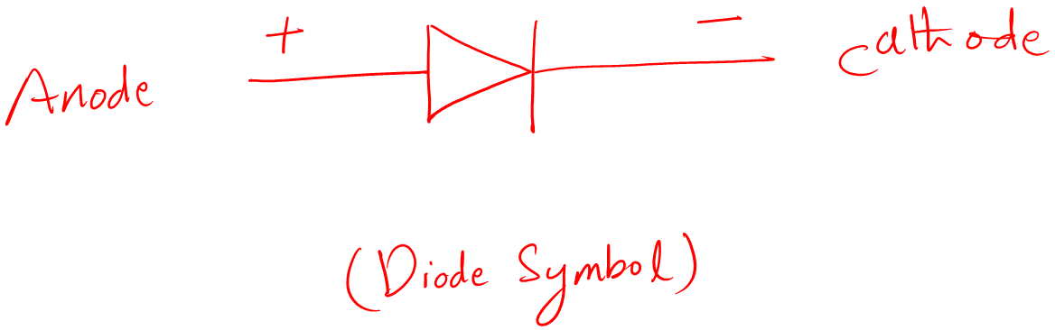
It is the first step in learning diode basics, to identify the symbol of a diode and remember it. There are many types of diodes. Each type has its own symbol, but the basic design remains the same. You will figure them out as we go further in the lecture.
You see the two terminals are mentioned in the above symbol diagram. The terminals are called anode and cathode. The anode is positive while the cathode is the negative terminal.
The question arises here, how do we identify the terminals in the physical diodes? Let’s find the answer in the following section.
Physical diode
We learned about the diode basic definition. Now, we really need to have a look at its actual physical appearance. So that we can identify it on various electronics circuit boards, or just use it in our electronics projects.
Following is the picture of the diode combined with its electrical symbol.
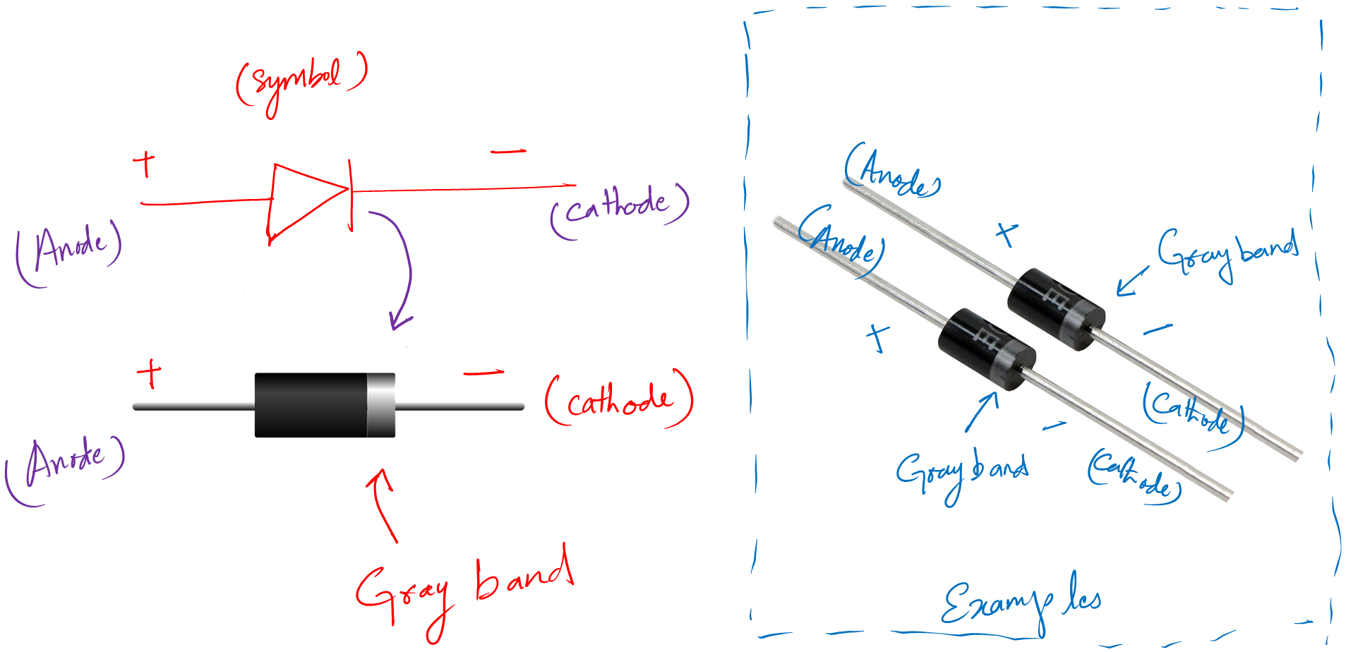
You see, it is like a small black cylinder. Pay attention to the gray line. The gray line always represents the cathode terminal. It will be a quick trick for you to identify the cathode terminal.
The above diode is through hole one. It is used in two-sided PCB boards or breadboards for prototyping. Apart from this, there exists a surface mount diode too. To identify its cathode, the same strategy is valid here too i.e., look for the gray line.
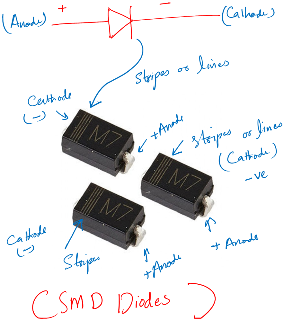
Moving on, I think it would be a cool activity if you could identify the diode yourself in the following picture. Can you tell me where is its cathode terminal?
Hopefully, you get the right answers. If not you can check out our detailed article on:
Now, we learned how a diode physically looks. The next interesting thing to learn is, how we can use it in our circuits.
To use it in a circuit, we have to learn about how we can power it up. What is the condition to properly power it up and use it in our circuits?
The answer is right here in the next section.
Diode forward and reverse biasing
When it comes to diode basics, you will hear these two terms all the time.
So let’s learn what is forward and reverse bias and how we can use them in our circuit design. These two terms mean how we connect our power supply across the terminals of the given diode.
a. Forward Bias
If you apply positive voltage to the anode and negative voltage to the cathode. You will see a current will start to flow through it. This specific operation is called forward biasing the diode.
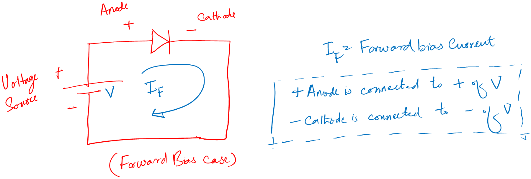
The current that flows in a forward bias condition is called a forward diode current. We use this bias all the time. In this bias, a diode acts as a close (ON) switch.
b. Reverse Bias
Similarly, if you apply a negative voltage to the anode and a positive to the cathode you are reverse biasing a diode.
And current following through the diode in reverse bias is leakage current. You know, this leakage current is too low, but sometimes we do consider it, and sometimes we neglect it.
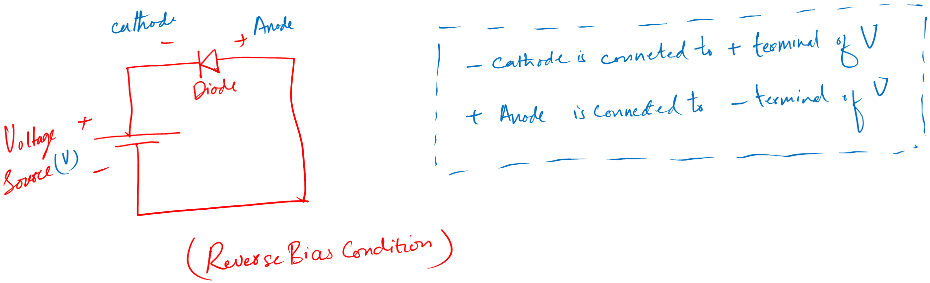
In the forward bias region, the diode can be considered a closed switch. While in the reverse bias condition, it acts as an open switch.
A diode would be in forward bias if the net voltage across the terminals is positive. i.e., it is forward bias even if the cathode has -10 and the anode has -5V.
So, to use a diode in a circuit you have to make it forward bias to pass a signal to the rest of the circuit.
We made it up to here in learning diode basics. You are doing very well. Now, let’s see the important relation between forward bias voltage and the diode forward current in the next section.
Diode VI curve
A VI graph of a diode shows a relation between the voltage across the diode and the forward current through it. It is a very important curve to understand.
Basically, it shows us that for what value of voltage we should expect to how much current will flow through the diode. And what is the voltage value we should avoid to save our diode from damage.
Following is the VI graph of a diode. Have a look at it and I explain everything about it.
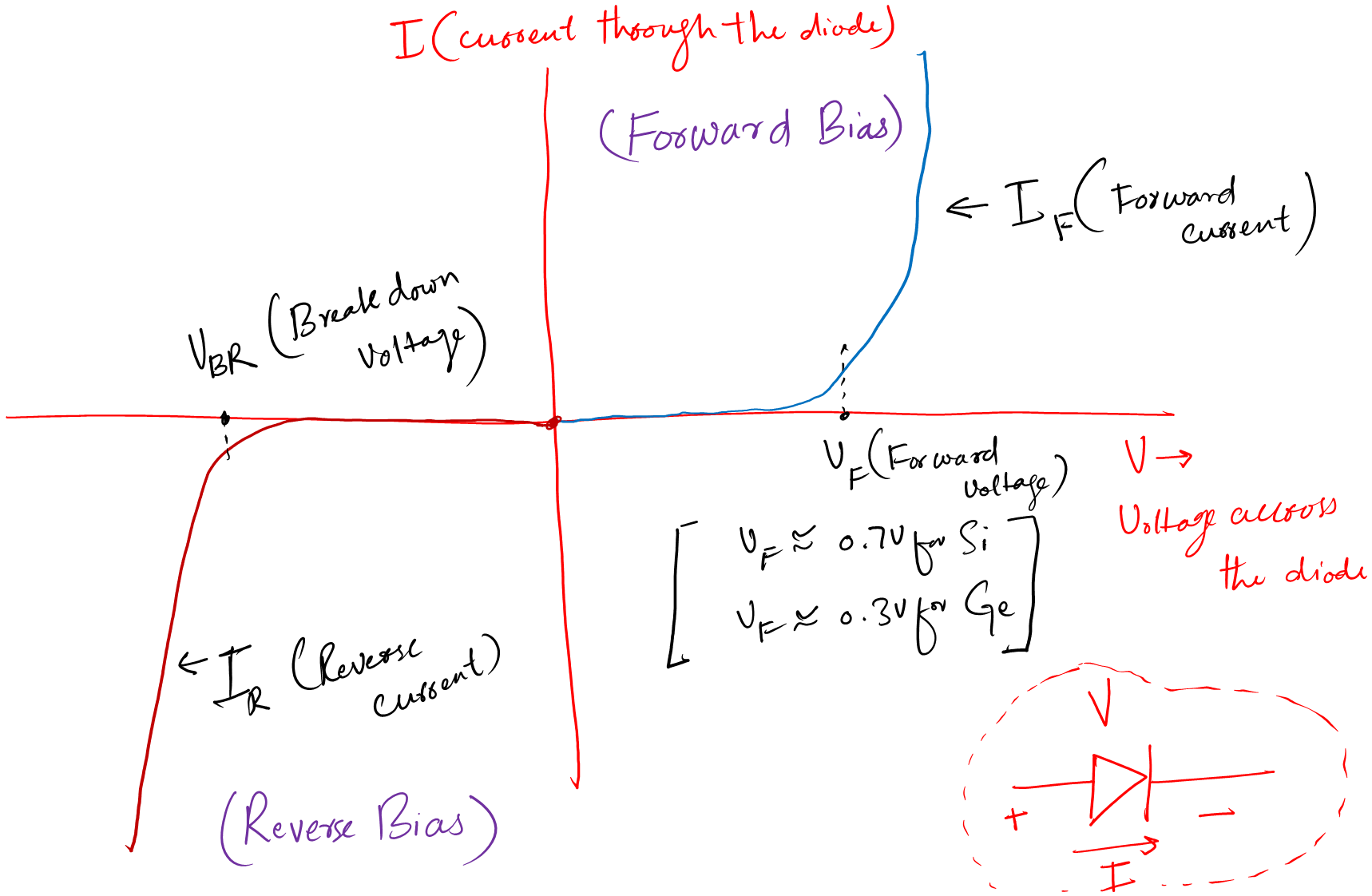
It is called the VI curve because at the X-axis you have voltage (V) and at the Y-axis you have current (I). The right upper region is the forward bias region. You can see that after the VF (Knee voltage), the forward diode current increased.
This means the diode is on and operating perfectly. Knee voltage differs for silicon (0.7V) and germanium (0.3V) diodes.
The left lower region is the reverse bias region. You can see a small leakage current there in the reverse region, but it is too low. In this state, the diode acts like an open switch providing an open circuit.
Be careful when you are in the reverse region. Do not apply reverse voltage more than VBR (Voltage at break down region). If you do so, you will burn out your diode.
Now, you learned how to use a diode in a circuit. The other thing is how to choose a diode according to the requirements of your circuit. To answer this you have to pick a diode capable of handling the circuit voltage, current, and power ratings.
Diode ratings
For proper operation of any device, you need to know its current, voltage, and power ratings. The diode ratings tell us the minimum and maximum quantity of the mentioned parameters to be applied to a certain device.
Current ratings of a diode tell us the minimum and maximum current it can support. And the same definition goes for the rest of the parameters.
The datasheet is the only source to find these ratings for any diode. Datasheets are made by manufacturers so that everyone can use them to make their projects perfectly without damaging any device.
Reading a datasheet is very important and sometimes people do not understand how to look for specific information in it. I am going to help you with this problem.
I will take the example of 1N4001, and I will show you how to read these parameters from its datasheet.
- First, you download the datasheet for your diode.
- Go to the section: “Maximum Ratings and Electrical Characteristics”. It is not necessary to be exactly like it. But I think you got the idea.
Diode datasheet reading
Following is the datasheet for 1N4001. Can you see the voltage and current ratings in it?
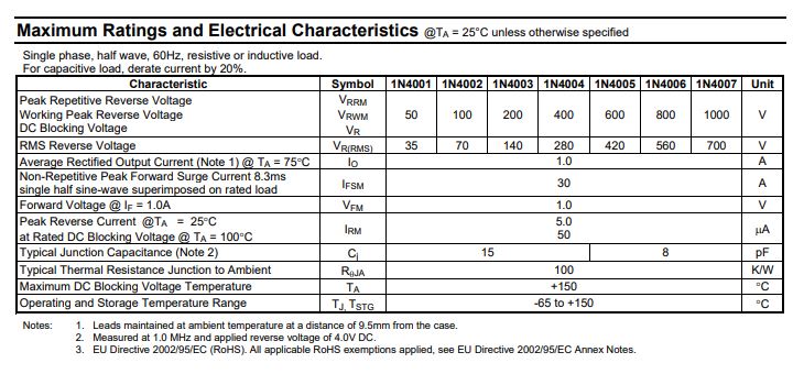
In the first row, the peak reverse voltage is given. This is the voltage across the diode when it is OFF (reverse biased). Do not apply voltage more than this, you can burn it out.
The second row gives the same information but in RMS terminology. RMS Reverse Voltage is the same as DC blocking voltage. The fifth row provides information about the maximum forward current a diode can safely handle. To limit this forward current, a series resistor is placed before the diode.
You may wonder about the power rating, right? We can simply multiply current and voltage to get the required power rating. For the present 1N4001 power rating is 50W (50V x 1A ).
You can see a peak reverse current in the sixth row. Here you can see yourself it is too low as I told you earlier. Always refer to the datasheet of your device. Do not apply voltage without proper information, chances are you may damage your device.
Diode testing
The goal of learning electronics and diode basics is to be able to use a diode for making our projects.
So, I believe up till now we have all the basic information about diode that is enough for a beginner.
We know what the symbol of a diode, what it looks like physically, we also know about the ratings so that we can properly use it without damaging it.
Before we jump into how to use it in a basic circuit, first we need to know if the diode we use is good or bad. We determine this by testing a diode first.
Two methods are mostly used to test a diode. Let’s talk about these methods.
a. Using a multimeter
Testing a diode means checking whether it’s working properly or not. An easy way to do it is by using a multimeter.
The following is the easy step by step approach to testing a diode using a multimeter.
- Take your multimeter and set it on the diode function.
- Then take your diode and connect in forward bias condition. This means connecting the black (-ive) probe of your multimeter to the cathode and the red (+ive) probe to the anode of the diode.
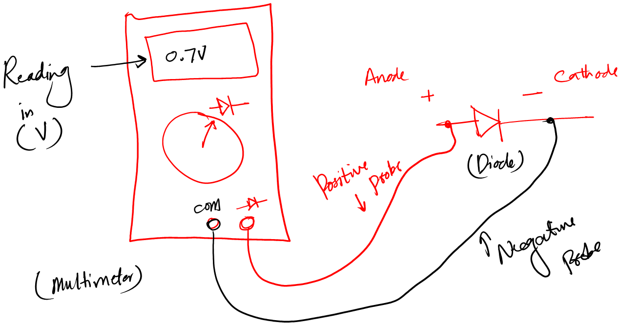
- If the diode is fine you will see a forward voltage drop between 0.2 to 0.75 V depending on the diode. Else your diode is a bad one.
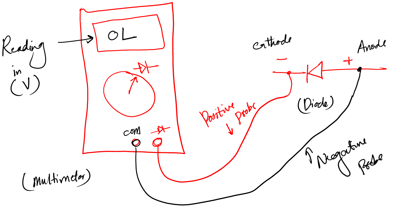
- Now reverse the diode. If it is a good diode, then you should have “OL” on your multimeter screen. Else your diode is a bad one.
b. Using a component tester
Besides the above method, we can use a component tester as well to quickly determine if a diode is good or bad. A component tester (Amazon link) is similar to a multimeter except we use it to check various electronic components.
- Take a component tester and place the diode in its socket
- Press the test button and see the results on the screen
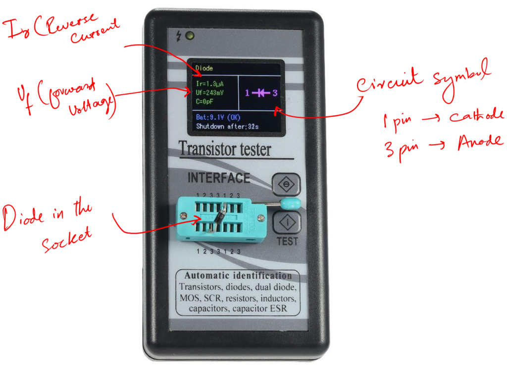
- If the diode is fine you will see its forward voltage value along with its circuit symbol
- The circuit symbol is useful when you have a diode where there is no gray band, and it is hard to tell which terminal is the cathode.
You can also check out our articles on diode testing and diode testing without a multimeter for deep learning.
Types of diode
There are a lot of different types of diodes out there in the market. The operation of diodes is almost the same, but their properties get changed. Some diodes are faster. Some have more power-handling capability.
Following is the list of all the different diodes.
- Zener diode: Allows current to flow not only from its anode to its cathode but also in the reverse direction. It is used in voltage regulations.
- Tunnel diode: It has a very fast operation, well into the microwave frequency region.
- Varactor diode: It acts like a variable capacitor under reverse bias.
- Schottky diode: It is a metal-semiconductor junction diode that consumes less power and has a high-speed switching capability
- Photodiode: It converts light into an electrical current
- PIN diode: It is suitable for attenuators, fast switches, photodetectors, and high-voltage power electronics applications.
- Laser diode: It produces coherent radiation.
- LED: It is short for Light Emitting Diode. Upon the application of forward bias voltage, these diodes glow and give light.
Diode functions in circuits
The diode is one of the most essential components of electronics. They are used for various functions in circuits.
Following are some functions of diodes.
- As a digital switch
- Handle high-power signals
- Safety
- Half and full-wave rectification
- Voltage multipliers
- Signal clampers/clippers
- Freewheeling
- Voltage regulation
- Signal peak detector
- RF variable attenuator
These are some functions of diodes, see our article Diode functions in circuits to learn how diodes perform these functions.
Diode basics circuits
Remember this diode basics for beginners, so please just go through the following circuits. Don’t try to focus on how the circuit works. Focus on general learning. Just learn the circuit name and what it does.
Following are a few basic diode functions of the diode.
- Rectifier circuits
- Voltage multipliers
- Protection of many other devices
- Clipper and clamper circuits
- Mixer circuits
1. Rectifier circuit
Every circuit needs power for its proper operation. And trust me almost every circuit works on DC power. But we all know AC power is coming to our homes, not DC power.
We need a third man to convert the coming AC to DC. This third man is a rectifier circuit.
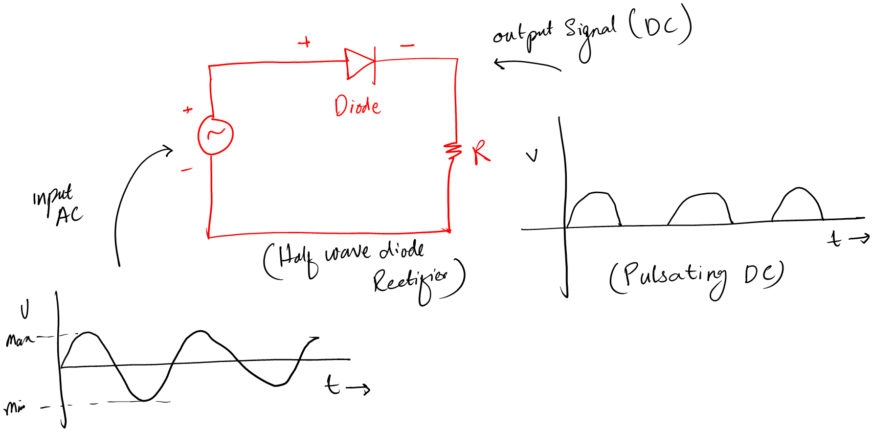
The rectifier circuit converts AC to DC so that we power up DC devices like our mobile phones. This rectifier circuit is made possible due to the invention of diodes.
It is a great application of diodes. Without a rectifier circuit, we would not be able to convert AC to DC.
2. Voltage multipliers
Sometimes we need different voltage levels in the same circuit. Instead of designing separate power supplies, diode voltage multiplier circuits are used.
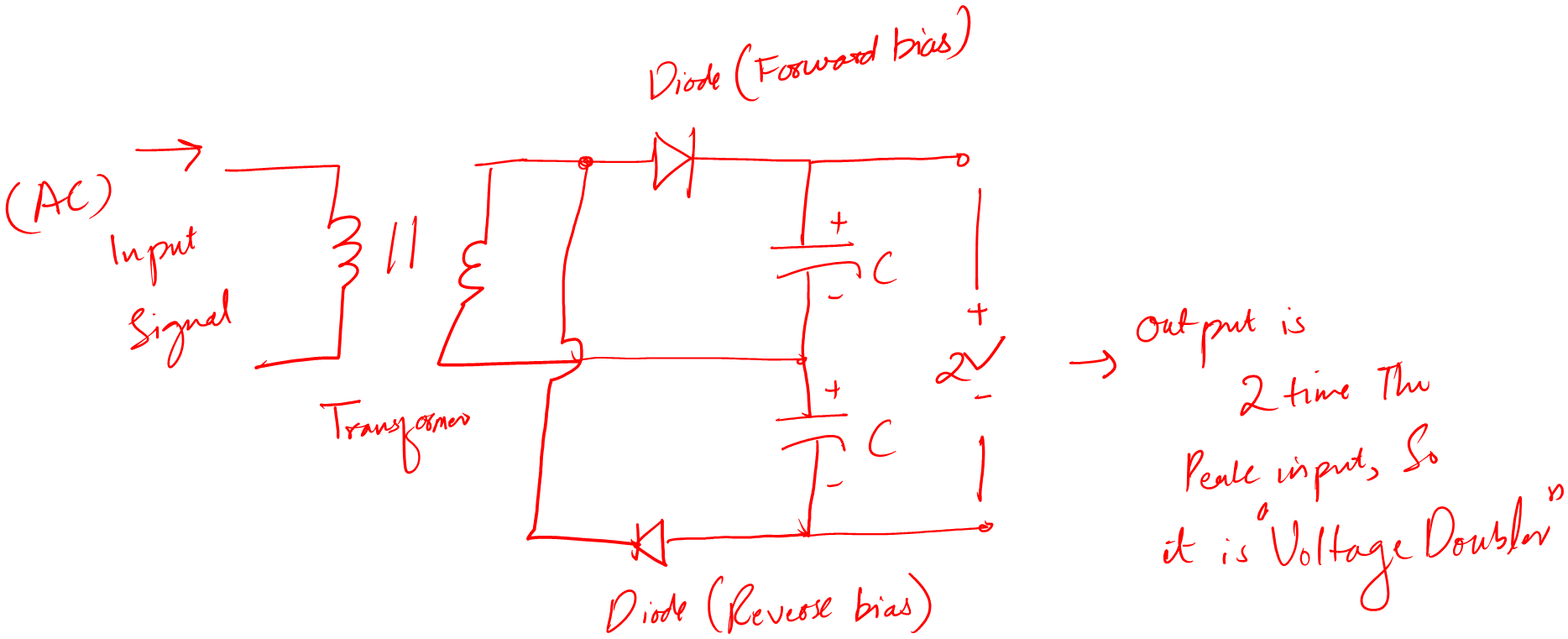
As the name indicates, voltage multipliers are a combination of diodes and capacitors that produce high voltage levels from a reference voltage level. In other words, voltage multipliers are used to produce high DC voltage levels from small AC voltage levels.
3. Clipper circuit
A diode clipper circuit is a simple circuit that uses diodes to limit or clip (cut) the voltage level of a signal. There are two types of diode clipper circuits, positive and negative, that limit the positive or negative peaks of the input signal.
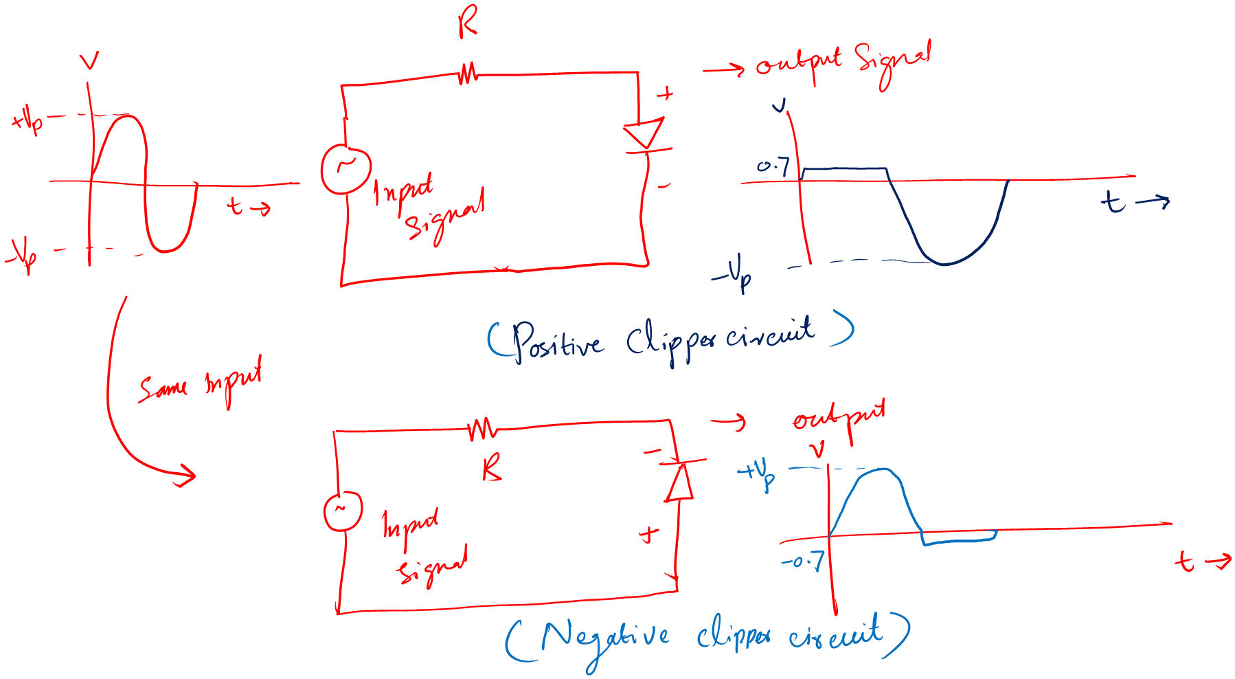
These circuits can be used for various purposes such as shaping waveforms, protecting signals, and changing voltage levels. They are commonly used in audio and communication systems.
4. Clamper circuit
These diode circuits are used to add a portion of the DC level to the existing signal. That is why they are called the clamp circuits.
We use these circuits to level up or level down a signal based on our application requirements. Also, we use these circuits to adjust the DC bias in amplifiers, limit voltage swings in analog circuits, and provide voltage regulation.
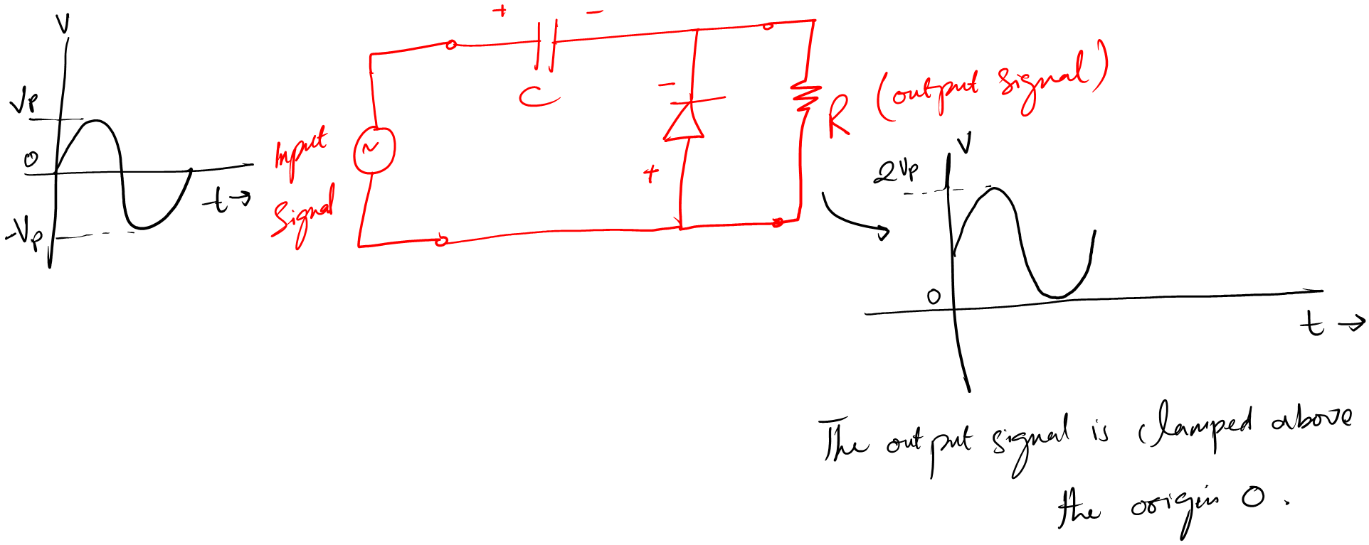
As you can see, a diode clamper circuit consists of a diode, resistor, and capacitor. When the signal is positive, it goes through the circuit and charges the capacitor.
When the signal is negative, the capacitor discharges through the resistor. This shifts the output signal up or down by a fixed voltage level, keeping it within a certain range.
5. Mixer circuit
A diode mixer is a circuit that combines two or more signals of different frequencies by using diodes, which allow current to flow in one direction. The diodes switch on and off in response to the signal’s polarity, creating new signals with frequencies that are the sum or difference of the original signals.
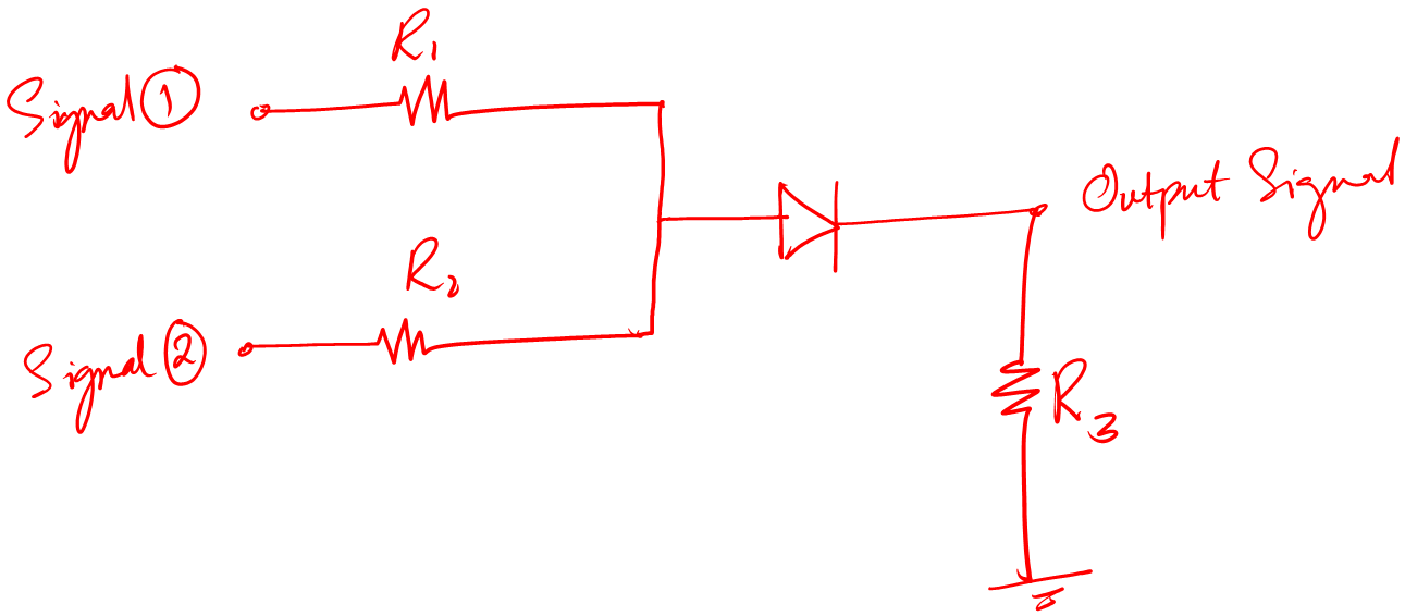
The mixer is commonly used in radio frequency and intermediate frequency systems because of its simplicity, low cost, and wide frequency range. It is essential in communication systems and other applications.
6. Protection
When working with circuits where there occurs a sudden change in output current, sometimes this change in output current goes back into the main circuit.
The back current can damage the circuit. To protect the circuit we use a diode. The diode used in this configuration is called a freewheeling diode and most of the time it is in reverse bias mode in normal conditions.
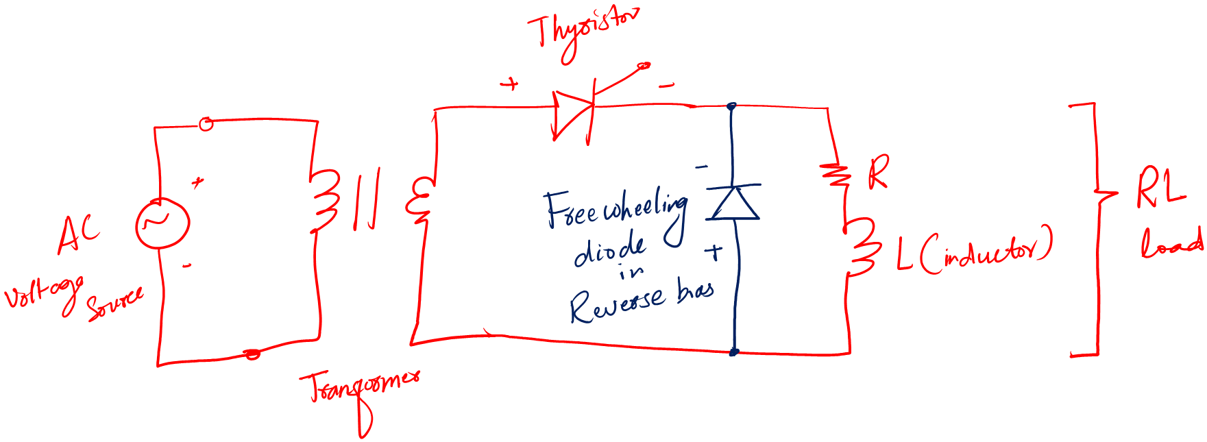
Moreover, when there is an inductor load or inductors in our circuit. Then because of a sudden change in current the magnetic field collapses, causing a voltage spike that can damage other components in the circuit.
For safety, a freewheeling diode is placed in parallel with the inductor to provide a path for this voltage spike to dissipate harmlessly.
As I said, the freewheeling diode is connected in reverse bias across the inductor. When the inductor’s current is interrupted, the diode conducts and provides a low-impedance path for the inductor’s energy to dissipate.
The diode remains reverse-biased during normal operation, so it does not affect the circuit’s performance.
Conclusion
I personally, found learning the diode basics very interesting. I remember my first power supply circuit design, diodes played a major role in that circuit.
However, at that time I did not have enough knowledge about it with time I learned a lot. And this post is all about what I have learned so far.
In a few lines,
- The diode is a semiconductor device that allows current flow in one direction
- There are two operating conditions of a diode 1) Forward bias condition and 2) Reverse bias condition
- When using a diode make sure you download its datasheet and check for its current, voltage, and power ratings.
- The gray bar on the physical diode represents the cathode terminal.
- You can actually test a diode by using any digital multimeter or using a component tester.
I believe that diodes are a fundamental component of electronic circuits that play a crucial role in controlling the flow of current and transforming AC to DC. Understanding how diodes work is an essential skill for anyone interested in learning about electronics.
Because diodes have many practical applications in electronics, including rectification, voltage regulation, and signal demodulation. They are also used in a variety of electronic devices such as radios, televisions, and power supplies.
So, that is it. That is all I want to share about the basics of diodes for a complete beginner. I hope you learned something from the efforts.
Thank you and stay blessed!
It is very helpful for students. Thank you for sharing your precious ideas and helping students to understand Electronics.
I appreciate it. Thank you