

A breadboard is a reusable tool for testing and making electronic circuits without soldering. It features a grid of holes with internal conductive strips to connect components like resistors and ICs. It’s perfect for quick modifications and experimentation.
Almost all of the basic electronics projects are first made on breaboard, which a lot of beginners have no idea of. In this article, we gonna see breadboard basics learn how to use it properly.
Let’s get started.
What is a breadboard
In simple words,
A breadboard is a very basic tool in electronics used to make circuit prototypes, to test our circuits, to compare the real-time results to simulation one, to build a part of a system and test it independently.
The definition is not that scary, just give it a time to digest. I am sure a lot of things will make sense to you as we go further in this article.
Why we use a breadboard
You got an idea to do an electronics project, awesome! But when you are actually doing it there are chances you may get it wrong the first time, the second time, the third time, or in the worst case you don’t get it right and you give up.
You made your circuit on simulation software, seems to work fine in software. Great! Now, it is the time to actually made it on something, the breadboard, and of course who says you won’t make any mistake. You will, and you will make a lot.
The point I am making here, in practice, there are chances of making good mistakes. And breadboard is the only guy there who can actually be very helpful to undo your mistakes.
We use a breadboard to make changes to our circuit much faster in case something went wrong and to compensate for our mistakes efficiently.
The other good point to use it is to avoid burning up your devices by directly going for soldering. We solder components once we are sure of our design.
Because once we are done with soldering it is very hard to make changes in the circuit. So, breadboard gives a solderless circuit making option which is great.
Now, we can say a breadboard is a solderless circuit making and testing device. Maybe if you are a newbie this concept may not be that easy to digest but you will get to know it once you do more projects and grasp more knowledge about electronics.
Different breadboard parts
Following is a full size breadboard. You can see its has different parts. It has a some numbers and a lot of holes.
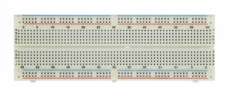
Just for information, there are many manufactures out there making different types of breadboard. So some breadboards may look different in size, color, or shape. But don’t worry they do the same job and are exactly alike when it’s coming to circuit prototyping.
- The horizontal lines of holes are called rows
- The vertical lines of holes are called columns
1. Power rails
The upper and below two rows of the breadboard are the power portions, called the power rail. Input power sources are attached to it and then distributed across the board by other external wires.
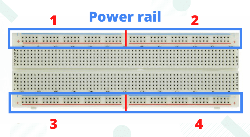
Further, each power rail is subdivided into two groups. In total there are four power portions. This way you can power the breadboard with different voltage sources.
Sometimes when you are working with a project, you may need different voltages at a time. This could be a problem, so to solve this issue in breadboard you have four different power portions.
Conventionally, the upper row is used for negative potential and the lower row is used for positive potential. It is a convention, you are free to do whatever the way you like it. But please be careful as powering mistakes can burn your circuit and you can harm yourself too.
If you connect a 5V to portion 1, then after the red line (see the above picture) in portion 2 there is no voltage at all. You can connect any voltage source to it, or you can copy the portion 1 into 2 if that is what your circuits demand.
2. The body portion
This the section where we make our circuit, make connections of various electronics components, connect resistors, capacitors, diodes, and integrated circuits (ICs).
You have to be very careful when working with it. In case you missed it, or make a mistake, there is a good chance you may burn your devices.
And let me tell you it is totally fine to make mistakes and blow up your devices. This is the way you actually learn concepts. I remember all my early mistakes.
Now I really laugh at them and remember how those silly mistakes have cost me of hundreds of rupees. But yeah, it was a learning journey, and still, it is.
Let’s take a look at it and discuss it in more detail below.
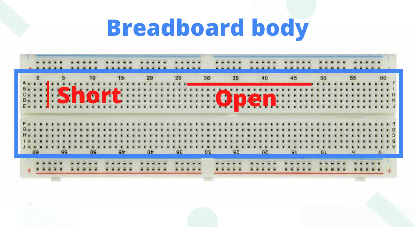
Column wise all the dots are short (connected) and row-wise all the dots are open. What does it mean? Well, it is that simple you connect a terminal of any device in any dot in any column, this means that now the entire column is the extended version of the terminal, connecting something to this column meaning connection it to the terminal of that particular device.
Pay attention at the side of the breadboard, you see there are labels from A to E and then from F to J. From A to E we count the number of rows is 5, and the number of columns is somewhat very large like its hard for me to count but still countable. Maybe if I counted it right it is a 5 x 60 matrix. The same goes for the other half i.e. from F to J.
3. Divider
Between the E and F row, there is a big gap, and it is differentiating the upper portion from the lower. It is called the divider. Between the E and F, we connect our ICs. Imagine if connect the IC in the upper or lower portion we will end in shorting the legs of IC and can damage it permanently.
So in summary, we connect the IC between E and F, and all other components in the upper and lower portion. The upper two rows and the lower two rows are the power rails to which we can connect four different power sources. The column is short and is open form the adjacent columns. A row is open except for the power rail.
Practice project
The cool thing about learning electronics is you don’t learn it properly without doing it. Or maybe I am the only guy that think it this way, correct me if I am wrong.
The best way to learn the concepts I discussed above is by doing a practice project. And then I leave it to you. My advice would be without practice it is really hard to grasp the concepts very well. So if you a chance to get your hands dirty with a breadboard, I will encourage it.
The LED circuit on a breadboard
This is the first project of almost every electronics beginner, its cool and awesome to do. I always get the feeling of that very day when I myself first made it in our lab.
It is so simple yet very fun to make. I strongly suggest to try it out yourself.
For the LED project, you need the following components.
- 5V battery
- 1kOhm resistor
- LED
- Breadboard
- Multimeter
Make sure you have these requirements in hand so that you can follow the video and try to make one for yourself. Don’t worry if you don’t access the mentioned devices just watch the project carefully and try to understand everything.
Hopefully, you have fun watching it. They’re much more to learn in the same mentioned course. I would love to see you learn electronics.
Breadboard care and maintenance
Breadboard is a regular tool. We use it a lot. Due to which breadboard requires some special care and maintenance, else it will become bad and we may have inaccurate circuit results.
If do not maintain the breadboard correctly it will lead to the following consequences:
- Poor electrical connections
- Can cause short circuits
- Poor maintenance can lead to components damage
- Will also reduce the lifespan of the breadboard
So, following are the some key steps that you should always keep in mind.
- Regular inspection of the breadboard
- Clean the board from dust and residue regularly
- Make sure to properly store the breadboard
- Always avoid excess force and pressure
- Use well-trimmed components while inserting it
- Take steps for proper heat management
Conclusion
Learning breadboard basics for beginners are very too fun. It is fundamental to learn how to use a breadboard when you are getting started with electronics. It is among those basic things you must learn if you want to understand the world of electronics in a better way.
In electronics, our job is to find a solution to a problem by using the laws and rules of electronics. When we are in the process of finding the solution we try different things and see what can work better for us.
In simple words we make circuits and hence those circuits are not the final products. We are subjected to make mistakes and to compensate those mistakes we make use of the tool, we call the breadboard.
A breadboard is a tool we use to make circuits without permanently soldering the circuit components. You can say it is a circuit prototyping device that makes our lives easy when it comes to electronics system design. A proper definition would be like, a solderless circuit making device.
Why we use it anyway:
- To make circuit prototypes
- To test our ideas
- To compare results with simulation
- To quickly fix the issues in the electronics system
- To have fun with electronics and make cool projects on it
So that is a little summary of what we covered in the article. Now if you the guy who loves to read the summary and then decides to go for the full article. Well, maybe this article would be fun so please read it anyway.
I hope the article kinda helped you and you learned a little from me.
Thank you so much and have a great life ahead.
**We learned about breadboard basics. You can keep learning by exploring what is the difference between a breadboard and s veroboard