

LED basics for beginners (Easy Guide, 2026)
LED in electronics is short for a light emitting diode. It is a diode, but it can emit Light upon the application of perfect bias voltage.
As LED emits light we use it mostly for indication purposes, to light things up, for decoration purposes, sometimes for testing circuits, and so much more. They come in various shapes, sizes, and various colors. Multimeter and componet tester are used to test LED functionality. They are widely used in lighting, displays, and electronic indicators due to their reliability and compact size.
In this article, we will learn about LED basics, its types, and how can you test it using different testing componets.
LED basics in electronics
Electronics is a very interesting field to take part in. It has so many interesting things to offer. All the beauty of electronics lies in its various electronics components, including LEDs.
We use and arrange various electronic components together and create circuits. These circuits become the core part of useful electronics products.
But if you pay close attention to various electronics products you will notice a lighting component. For example, if you look at your TV. When it is OFF there is a red small light in its corner but when it is ON it turns green. These lights are telling the state of the products – thus playing a key role.
These small lights are called LEDs in the electronics world. Now the TV example is just one daily life example. You can encounter such lights in your car, mobile, in many other products. You got the point.
Now to properly define an LED, it would be like the following:
An LED in electronics is a semiconductor device that emits light when it is forward biased.
Following are the LEDs in action in real time.
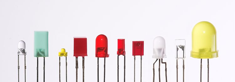
You can see they come in various shapes and sizes. This is because every electronics product has its requirements and demands. Also, keep in mind they come in multiple colors as well.
Circuit symbol
So above we look at the basic definition of LED. I hope you got a basic understanding there. Now let’s talk about its circuit symbol.
A circuit symbol is very important to remember about each and every electronic component. This helps us to differentiate each component from one another. Also, it helps us draw circuit diagrams.
Following is the circuit symbol of an LED.
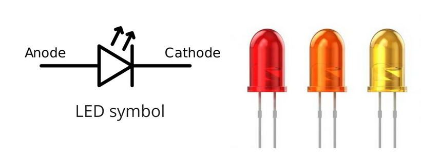
As LED is a type of diode. You can see its circuit symbol (on the left) is similar to a diode. But as LED emits lights that is why there are two arrows representing the light emission.
The horizontal line in the circuit symbol represents the cathode (negative terminal). The other terminal is the anode, the positive terminal.
Remember this circuit symbol and draw it a few times on paper so that so don’t forget it in the future.
Identifying the correct terminals of LED
When working with LED in real time for making DIY circuits or repairing a circuit. The challenge you will face is the correct terminal identification.
By correct terminal identification, I mean to identify the cathode and anode.
As LED is a diode if you don’t connect the right terminals to the power supply it will not work. And in some cases, you may damage it permanently.
So how do correctly identify the right terminals? Follow the following guidance.
a. For new LEDs
It is easy to identify the anode and cathode for a new LED. A new LED always comes with one leg longer than the other. See the following example for your reference.
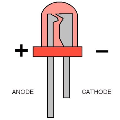
The longer leg is always the anode (positive) while the shorter is the cathode (negative).
b. For used LEDs
Now when a LED is already used in a circuit board the legs can not be trusted anymore. As the legs are cut out.
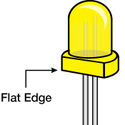
This can be true for off board LEDs as well if their legs are of the same length, or you are not sure about the length.
In the above cases look for the cut side of the LED. This trimmed or cut, or flat edge side is always the negative cathode. See the following example for your understanding.
I would recommend getting yourself some LEDs and doing some experiments with them. That is the only way you will learn the concepts I shared.
For more deep understanding for LED pin identification, check out the article:
Biasing an LED
Now that we got the idea of LED and correct pin configuration. It is time to power it up and see some colorful lights.
The biasing (in simple words connecting the power source) of an LED is just biasing a diode.
To light up an LED we need to connect in if forward bias. By the forward bias I mean we need to connect the anode to the positive terminal of the voltage source and the cathode to the negative terminal.
See the following circuit in which LED is connected in the forward bias:
I strongly recommend making this circuit yourself. This way you will learn how to correctly work with any type, shape, and color LED.
Please do not connect the LED in reverse bias. In this bias, chances are you may damage it permanently. Also, do not apply high voltage in the forward bias more than the LED is rated for. Ratings of any LED can be found in its datasheet.
LED ratings and safety measures
LEDs are no different from other electronic components. They have their ratings. By ratings, I mean what should be the right voltage and current applied to the LED for its proper operations.
Consider ratings as the maximum and minimum values of certain parameters (like the voltage, current, power, temperature, etc.) you must follow to properly operate an electronic component.
To find out about the ratings of your LED in electronics. Go to its datasheet and there you will find all the data you need to know.
Particularly with LEDs, we are interested in the forward current (If) and applied voltage (Vf) value. Let’s say the datasheet of a particular LED in electronics says the maximum forward voltage is 5V and the maximum forward current is 200mA. We should never exceed these values else we will have a damaged LED.
Also, we should also look at minimum values as well. If you apply voltage less than the given minimum voltage the LED will not work for sure.
Check out our article on LED ratings.
Now as we get ourselves introduced to ratings. The question is how we can design a circuit that will limit our circuit in these given ranges so that we can safely put our little LEDs for lighting.
The answer is by putting a limiting resistor in series with the LEDs. This limiting resistor value is calculated so that it will never allow the current that the LED can not handle.
See the following example for your reference.
So when you are working with LEDs please make sure you use a series resistor with all of them to ensure their safety for the long term.
Application of LEDs
There are so many applications of LED in electronics. But mainly LEDs are helpful for the following:
- Indication purposes
- State representation of a circuit or product
- Decoration purposes
- DIY projects for electronics
- Circuit testing and analysis
- Indication signs and boards
LED testing
This is a really important section to focus on. When working with LEDs the first thing is to ensure whether it is good or bad. We do that to save our time and resources.
For example, if you put a bad LED in a circuit and permanently solder it. Later on, you find out the LED is bad, then you just wasted your energy and time.
So it is essential to first test an LED and then use it in your circuits. This testing is also applicable to old LEDs. In fact, old LEDs should never be reused without testing them.
Let’s see how we can test an LED and you can also check out our detail article on LED testing.
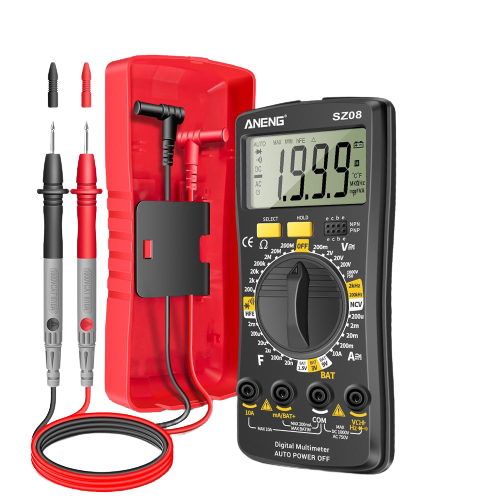
a. LED testing with a multimeter
A multimeter is a very fundamental tool when it comes to electronics. You know in electronics we deal with various resistance, capacitance, voltage, current, and so much more.
To measure the above mentioned parameters we use a multimeter. A multimeter helps to measure the value of resistors that we are going to use in our circuits and projects.
Briefly, the multimeter is used to measure the following. Don’t worry if you are a complete beginner and don’t know about the following just yet. Just remember the multimeter as a measuring tool.
- Resistance of a resistor
- The capacitance of a capacitor
- AC voltage and currents
- DC voltages and currents
- Circuit continuity
- Diode testing
- Transistor testing
- Frequency measurements
- The inductance of an inductor
- and much more
You see that it is that fundamental tool that you must have for your lab. Without it, your learning journey of electronics is incomplete, at least in my opinion.
No to use a multimeter to test LEDs is simple just follow the following steps:
- Foremost, take your multimeter and set it to the diode test function
- Take the LED which you want to test.
- Let’s connect the LED in the forward bias case.
- Forward bias case: Connect the red probe (+ive) to the anode of the your LED. And connect the black probe (-ive) to the cathode of the LED.
- Take the readings.
- Reverse the probe connection, i.e., make the LED reverse bias.
- Again take the readings
A good LED will show you reading between 0.4 to 0.8V in the forward case and will show OL in the reverse bias case
However, a bad LED will show OL in both cases. This means your LED is a bad one and need to be replaced or should not used in any project or circuit.
Remember in diode test mode on multimeter the results showing on the display are in mV range.
b. LED testing using a component tester
The above multimeter method requires careful readings. And it is subjected to human errors. Also, you need to have an understanding of how to use a multimeter.
I am not saying the above methods are bad or something. I am just saying we have an easy alternative to the above – that simple.
This method requires a new tool called the component tester. This component tester is an amazing and fun tool to have in our labs. It makes our lives easy and most importantly, it shows we have a deep love for electronic devices.
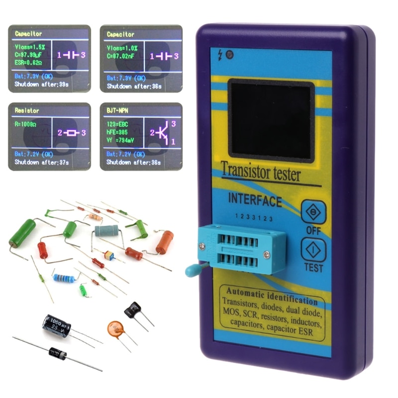
Following are the steps to use this tool for any LED testing:
- Turn on the tester
- Place your LED you want to test
- Press test button
- See the results on the screen.
- If the LED is fine you will see a forward voltage drop of 0.7V for Si and 0.3V for Ge.
- If the LED is bad you will see no results – it is that easy.
As this method seems interesting. And you should try this definitely. But this method has a fundamental limitation. You can’t use it for in-circuit testing.
Now, if the component tester mentioned above has got you curious and want to know more about it. Here is the link, M328 Component Tester (Amazon link), for your own further research and investigation.
Conclusion
LED in basic electronics is short for a light emitting diode. It is a diode, but it has the capability to emit light when forward biased.
Most LEDs have two terminals called the anode and cathode. An anode is the positive terminal while the cathode is the negative one.
To properly bias an LED cathode must be connected to the negative terminal of the voltage source while the anode must be connected to the positive terminal. If you don’t follow this rule your LED will not work and in some cases, you may damage it permanently.
If we talk about the application of LEDs we will agree the most important role of LEDs is the indication. We use it for indication of various states of a circuit. We use it for decoration and so much more.
Now, working with LEDs are just like working with diodes. I would suggest please carefully test as LED before using it in your circuit especially the old one.
So for testing LEDs we can use either a digital multimeter or a component tester like an m328 tester. Both these testing methods are explained in detail in the above sections.
That is it. That is all I have to share about LEDs in electronics. I hope you enjoyed it.
Thank you and have a grateful life.
Other useful posts:
i really like your books
Thank you 🙂