

Electronic Components Testing (Step by Step Guide, 2026)
Electronic components testing is a process to know if the components are working fine or not in the circuit or off the circuit.
The steps of the testing process vary from component to component. But in my experience, these steps are easy to follow and remember. And you will become good at testing electronic components with time.
Practice is the key.
To successfully conduct a testing process, we need to have basic electronics test equipment in our lab. This is mandatory. Some basic testing pieces of equipment are the multimeter, ESR meter, Oscilloscope, capacitance meter, Ohm meter, and much more.
Now, there are so many electronic components out there. That is why this article will be a long guide that will walk you through the testing process of each component step by step.
If the above introduction has got your attention, and you are an electronics beginner or hobbyist. Then I am sure you will like the rest of the article as well.
At the end of this article you should be able to:
- Know the general process and theory of testing various electronic components
- Tell if a resistor, capacitor, inductor, transistor, diode, LED, and IC is good or bad
- Use a multimeter for testing effectively
- Learn how to use a proper component tester and ESR meter
- Use IC tester for integrated circuit testing
- and so much more
Sounds interesting? Then, let’s get started.
Electronic Components Testing Theory
Before getting into any specific electronic component testing process. It is important that we understand the testing process in general.
This general process will help us in the long run. As it will make us prepare for unseen or uncertain situations throughout our career and working with electronics.
I believe the first step is to identify the nature of the component.
1. Component nature
What do I mean by this? Basically, there are two types of electronic components. One group is called the Active Components while the other is called the Passive Components.
Active components are those that need external power for their operations. They provide some type of gain to the circuit. Example are:
- Transistors
- Operational amplifiers (Op-Amps)
- Integrated Circuits (ICs)
- MOSFETs
- JFETs
- IGBTs
- SCRs
While on the other side, there are passive components. They don’t need any external power for their proper operations. And don’t provide gain, in fact, they dissipate power. Examples are:
- Resistors
- Capacitors
- Inductors
- Switches
- Connecting lines
- Diodes
- Transformers
- Relays
Categorizing the components this way is the key to accurate testing results. So as a beginner, first know what type of component you are dealing with.
2. Component technology
Now, besides active and passive. There are two very important technologies used for the making of electronic components.
They are:
- Through holes components
- Surface mount devices (SMDs)
Through hole components are those which have thick terminals you may say legs that go through the holes of PCBs.
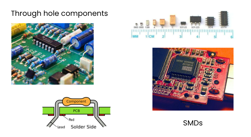
While on the other hand, SMDs are soldered on the surface of the PCBs. Both components have their own uses and advantages.
It is not like which is better – it totally depends on what you are designing. Through holes are mostly used for handling high power while SMDs are preferred when we want a compact size product.
The technology type doesn’t really change the testing process for the same component.
For example, no matter if you are testing the SMD resistor or a through hole resistor. The testing steps and process remain the same. Yes, a slight change will occur in the equipment probes and sometime you will need a whole new test equipment.
3. General methods for electronic components testing
Alright!
So, you now know that first, you will identify the component nature and then the technology. After that, you will apply the following methods.
First, let me discuss these methods in general. Then in the below sections, we will adjust these methods according to each specific component.
a. The Visual Inspection method
As you can guess from the name, it is the method of generally seeing a component with our eyes.
In this method, we inspect the component, both in circuit or off circuit, and see for the following obvious scenarios:
- If it busted open
- There is any leakage
- If it is broken,
- If there are any visible crakes
- If the color has changed
- If there are some burning symptoms on the PCB near the component
- If there is any naughty smell
- Upon turning the circuit there are some strange sounds coming from the component
- Also, the inner guts that you feel inside your heart about the component
If there are any of the above situations, then it is time to directly replace that component if it is inside a circuit board. Or don’t even think to use that component if it is off the circuit.
b. Using the test equipment
Most of the time a component will be detected from simple visual inspection. But it is not true for all cases. Then test equipment is the way to go with.
By the way, test equipment alone can’t help you if you don’t have the right knowledge about the circuits. So, I am assuming you already know exactly which component you want to test.
Alright!
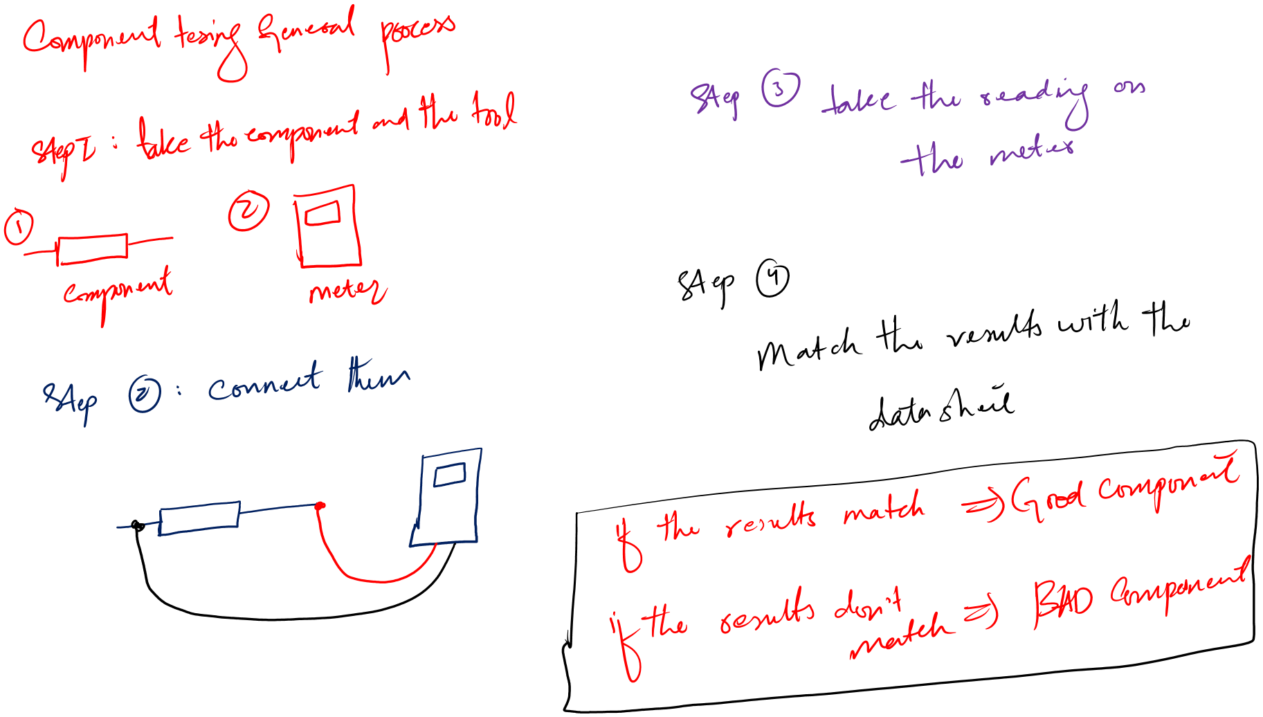
In general, every testing of a component using any testing equipment goes like this:
- You take your component and the required test equipment
- For example, for resistor testing: you take the resistor and the multimeter
- You connect the component to the equipment in the required way
- You take the reading on the screen of your device
- Using the knowledge you then compare the reading with the exact reading (you already know or given by the manufacturer)
- If the reading matches the exact reading, you have a good component, else it is a bad component
Electronics is a huge discipline. Its subfields range from circuits theory to advanced applied electromagnetic. For these reasons you have to have the required testing equipment which totally depends on what subfield you work in.
4. Right Test Equipments
I am writing this article for beginner people. People in this group fall into low frequency circuits. Which means we will only need the following tools.
- Digital Multimeter
- Component tester
- LCR Meter and tweezers (SMD component testing)
- IC tester
- Oscilloscope and a function generator (for advanced testing, totally optional for beginners)
Just for extra knowledge. If your components are high frequency then you should have a working spectrum analyzer and vector network analyzer (VNA) as well for the measurement of S-parameters and reflection coefficients.
a. Digital multimeter
When it comes to electronic components testing, a digital multimeter is the must have device. I believe without this tool you will have a hard time testing the components.
Now, what is a digital multimeter?
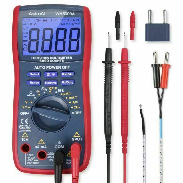
It is an electronic measuring device that can measure the following quantities with high accuracy:
- Resistance of resistor (both through hole and SMD resistor)
- Voltage and current measurements for both AC and DC
- Continuity testing
- Capacitance measurements
We will use this device a lot in this post.
b. Component tester
A multimeter is good, but it requires you to have enough testing knowledge about each component. For example, for a resistor, you must be able to tell which reading on the multimeter means it is a good resistor. And which reading means the resistor is bad?
And the same goes for every component.
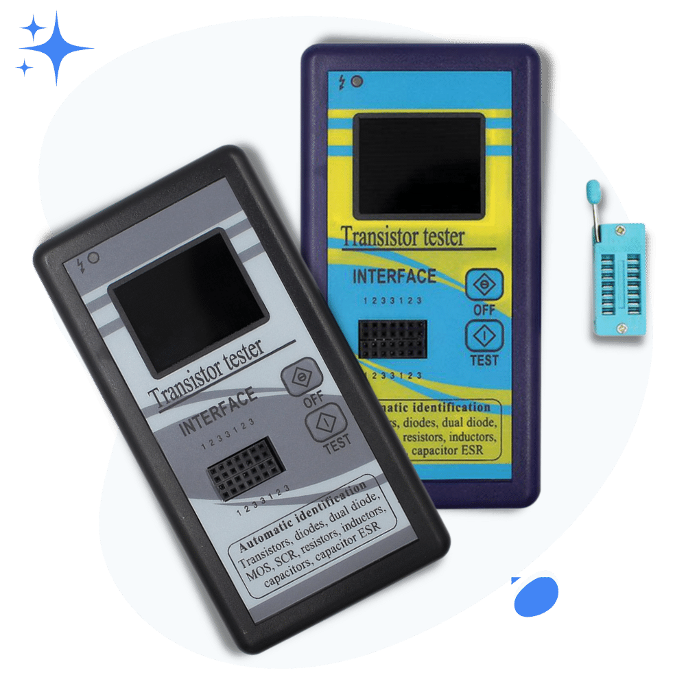
To tackle this we need to have another tool, called the component tester. It directly tells us which component is good and which is bad.
This doesn’t mean this device will eliminate the need for a multimeter. No, because it is not best for measuring voltages, current, and in circuit component testing.
Each device has its own pros and cons, it totally depends on the situation.
c. LCR meter or tweezers
Multimeter and component tester can help you. But when it comes to onboard component testing, you are in need of an LCR meter (best for through holes) and an LCR tweezer (best for SMDs).
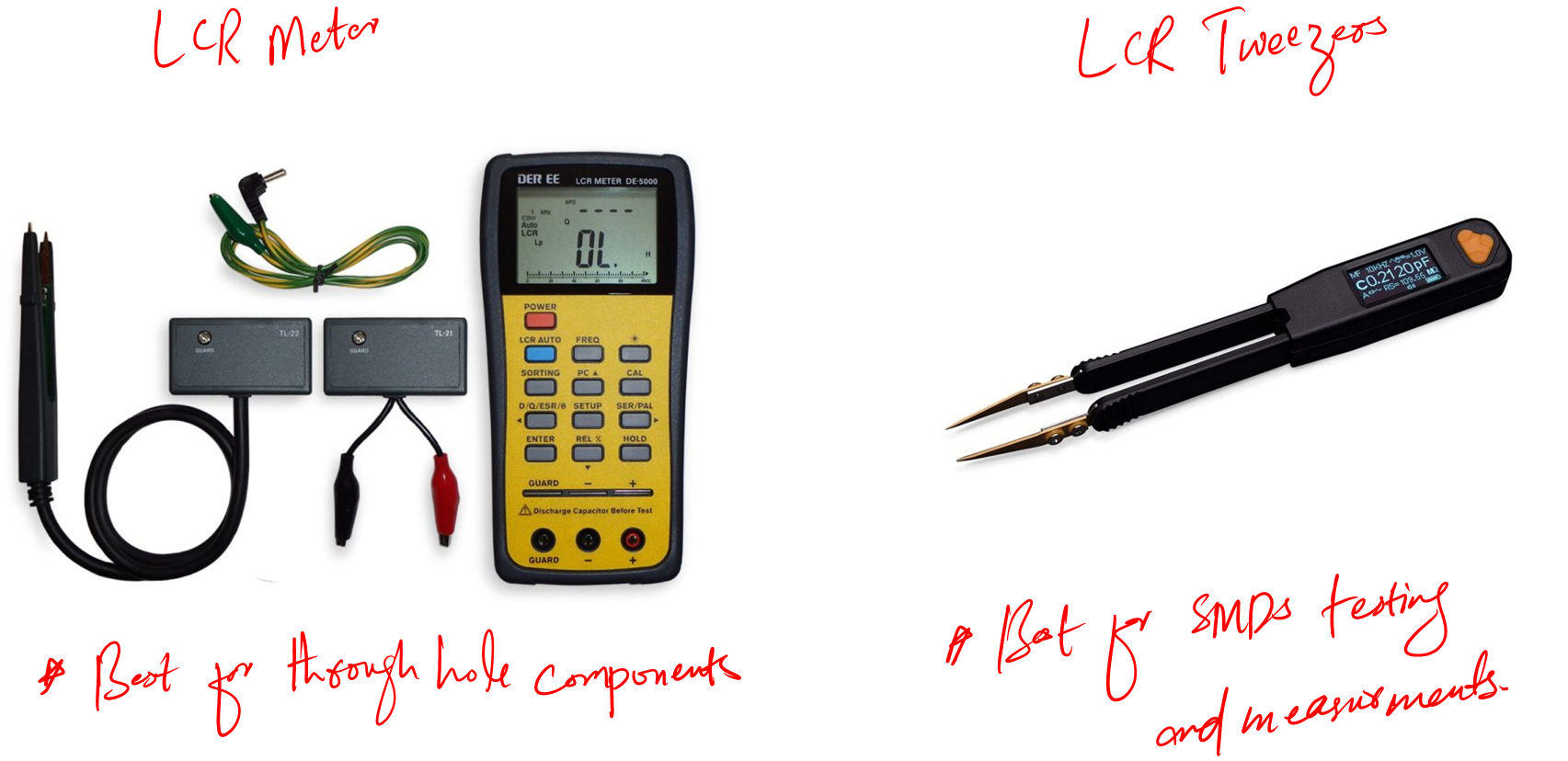
Well, if you have LCR meter then just by using tweezer probes you can test the SMDs with the same meter. But it is good to have a dedicated tool for SMDs as it is very convenient to use.
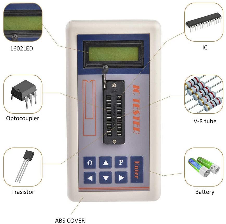
d. Integrated circuits (ICs) tester
You know, a circuit has capacitors, inductors, resistors, connecting wires, relays, transformers, diodes, transistors, and connectors. For all these the above devices are enough.
But there is a single piece missing, and that is integrated circuits. Integrated circuits (ICs) are almost everywhere in electronics. I am sure you have seen them plenty of times. They look like black small boxes in electronic circuits.
How to test those?
Well, you can use a multimeter for testing ICs as well. But this is not very efficient. For this, we should have a dedicated IC tester.
IC itself is a discrete circuit with its own functions and feature. We use ICs in circuits to reduce the circuit space and improve efficiency.
Alright!
We are done with basic equipment that I believe is a must for a beginner. Now let’s get into how to use these tools to test various electronic components.
1. Resistor testing
A resistor is the most used electronic component. It is a two terminals device with the ability to resist the flow of current through it.
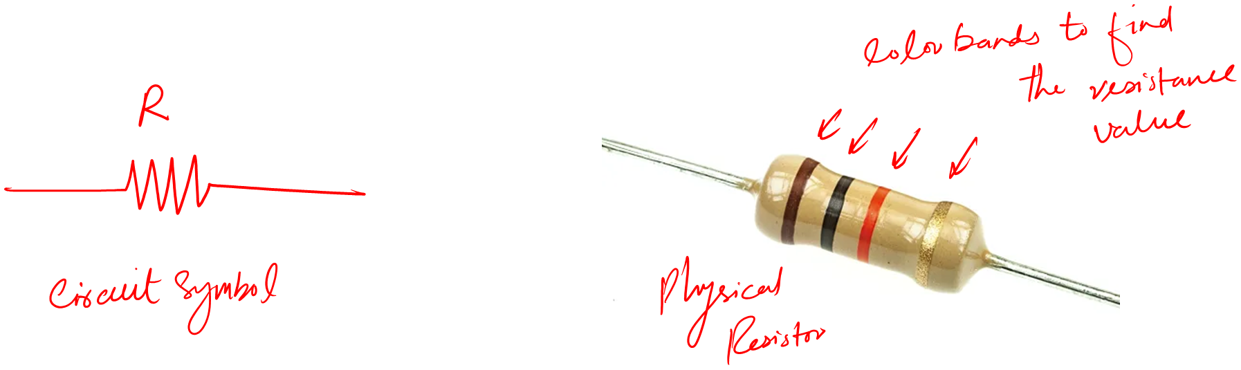
Above is the circuit symbol and some real-time resistors. One thing to remember about resistors is, that they are passive components.
We use a resistor to protect a circuit or a portion of a circuit from overcurrent flow. It is like a safety device against large unwanted currents.
Now, there are many types of resistors out there but all types serve the same function, i.e. to resist the current flow.
Let’s see how we can test this electronic component to see if it is good or bad. You must always test a resistor before putting it in any circuit.
The reason is if it’s a bad one, especially a short one then there is a chance you can damage your circuit due to over-current flow.
Method 1: Visual Inspection
In this method, we look for some obvious signs that help us to identify any bad resistor individually or inside the circuit board.
Following are the few signs you should look for:
- The body of the resistor may be blown
- The resistor may be busted open
- There is a crack in the body
- If the resistor is on PCB and the PCB color has changed to black around the body or terminal of the resistor.
- There is a change in the color of the resistor
I think we need to look at some examples of bad resistors so that you can exactly know what I am actually talking about here.
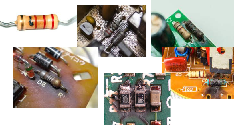
You can clearly see the differences.
Now, in general, you can spot a bad resistor by visual inspection in no time. There might be cases where you will not be able to find the above signs useful.
Then you have to use your own judgment. But I am pretty sure a bad resistor will show itself to you if you pay a little attention.
Method 2: Using a multimeter
So, the resistor has no obvious signs. Then we can use a multimeter to find out if it is good or bad. Let’s say we have a 1K resistor under the test. We know this value from the color code of the resistor.
Follow the following steps for this method:
- Take your multimeter, below is my KM601 (Product link), and set it to the resistor function
- Take your resistor and connect it to the probes of your multimeter
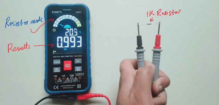
- Note the reading carefully
- Read the color code of your given resistor.
- Compare the color code value with the actual reading of the multimeter.
- If these values match with the given resistance tolerance range, you have a good resistor, else your resistor is bad.
You can not use it for in-circuit resistor testing. Because in circuits resistors are connected with other electronic components as well.
If you try to measure resistance that way, chances are you will get an equivalent component’s resistance rather than the specific resistor value. This may lead to the bad judgment of a resistor.
For an in-circuit resistor, first, desolder the resistor from the circuit, test it, and then resold it back if it is a good one.
Types of bad resistors: Basically, there are two types of bad resistors:
- Open resistor
- Short resistor
The open resistor shows “OL” on the multimeter screen. While a short resistor shows “0” zero resistance on the multimeter.
So, for in-circuit resistor testing, we are interested in these two types. We follow the same steps as above and see the results if it is an open or short resistor. If not then the value of a good resistor is in the proximity of the actual value (depending on which type of other circuit elements are there near to it).
For example, a good 1K resistor should give you a value of around 850 to 999 Ohm. Please don’t forget to turn off your circuit (take off the battery) before using the multimeter or measuring any value.
The same process applies to SMD resistors as well.
Method 3: Using a component tester
Now, this last method is very interesting. Exciting in the sense it is a new way of testing electronic components. To perform this method I am using my M328 component tester (Amazon link).
Follow the following steps to perform this method:
- Turn on the component tester.
- Put the resistor (1K that I used above) you want to test in the socket of your tester.
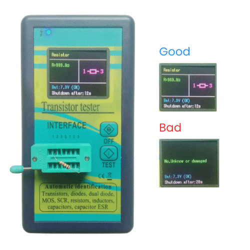
- Press the test button.
- See the results on the screen.
- If the resistor is good it will show you its value. If it is bad, it will tell you that the resistor is bad – it is that simple.
The limitation of this method is you can not use it for in-circuit resistance testing.
Other than that it is a very easy and straightforward method to apply. It will save you a lot of time and resources.
2. Capacitor testing
A capacitor is another fundamental level component. It has two terminals and acts as a passive energy-storing device.
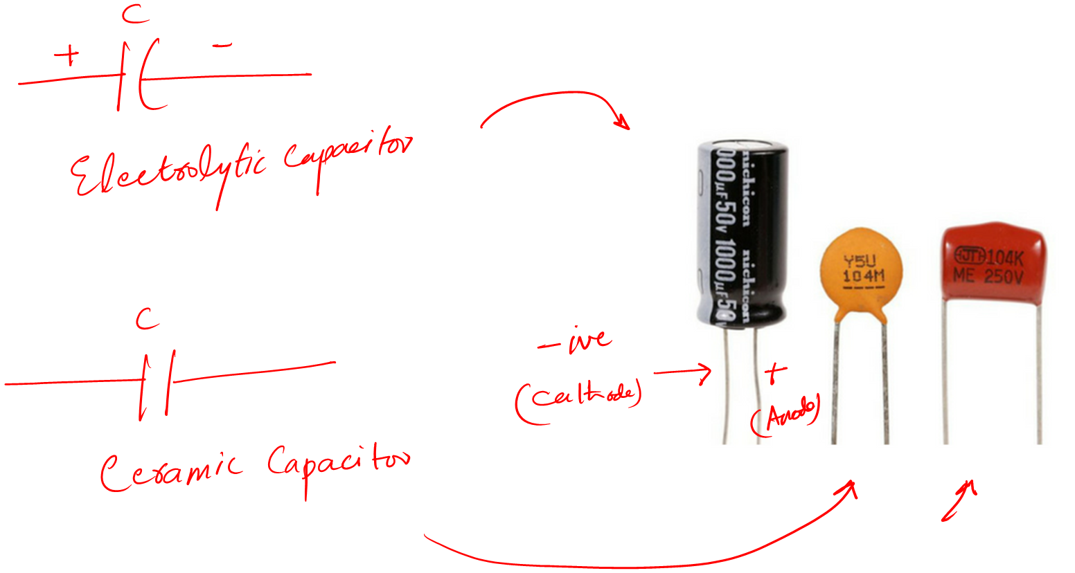
It has two types. The electrolytic and the ceramic type.
The electrolytic type capacitors are polarity dependent meaning that they have positive and negative terminals.
While ceramic capacitors are independent of polarity. You can connect them in the circuit without worrying about their positive or negative terminals.
Let’s see how we can test it.
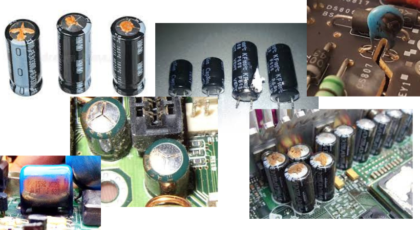
Method 1: Visual inspection
In the visual method, we look at the capacitor and try to see the following signs:
- Is the body of the capacitor is busted
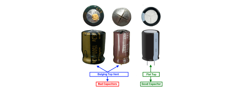
- Is the top side is popped up
- Is there any leakage in the body
- Is there any bump anywhere on the body of the capacitor
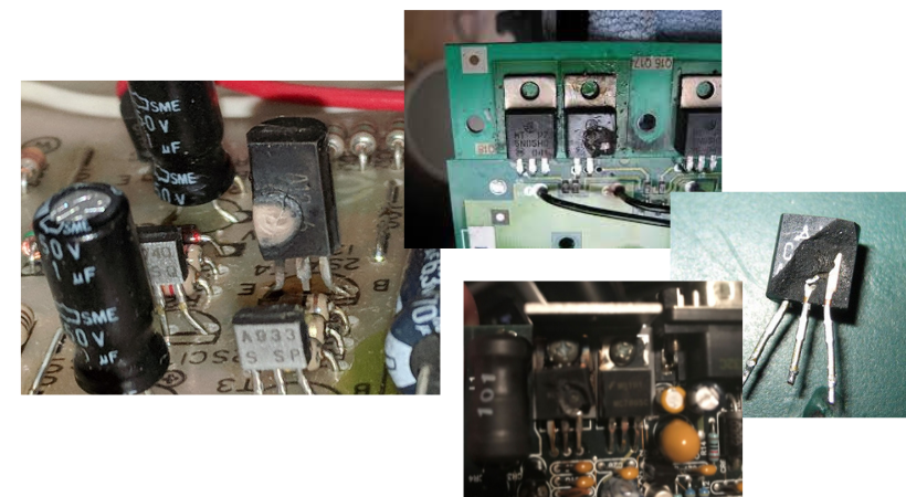
Following are some examples of bad capacitors solo and inside the circuit board.
You know, capacitors are most of the time used at the front end of the device. The reason is that they are good at filtering out the noise from the comping signal.
Also, they try to make the signal as smooth as required by our application.
Since they do a hard job. With time their performance degraded and need to be replaced by new capacitors.
So to apply the visual inspection on in circuit capacitor. Look for the front-end big capacitors first.
Usually, they are the capacitors that act badly and due to them, you are not getting the desired outcomes.
Method 2: By using a Multimeter (Off circuit capacitors)
The obvious bad capacitors will be filtered out by the above visual method. Now, we will see how to work with a physically looking bad capacitor. There are several ways,
- Off circuit capacitor testing
- In circuit capacitor testing
For off circuit capacitor, we can use a multimeter or a capacitance meter.
Follow the following steps for this method (using a multimeter):
- Take the capacitor and your multimeter
- Set the multimeter to capacitor mode
- Measure the capacitance value with your meter by connecting the black (-) probe to the negative terminal of the cap. And also connect the red (+) probe of the multimeter to the positive terminal of the capacitor.

- Following is a real time example. Please discharge your capacitor first, or else it can damage your multimeter.
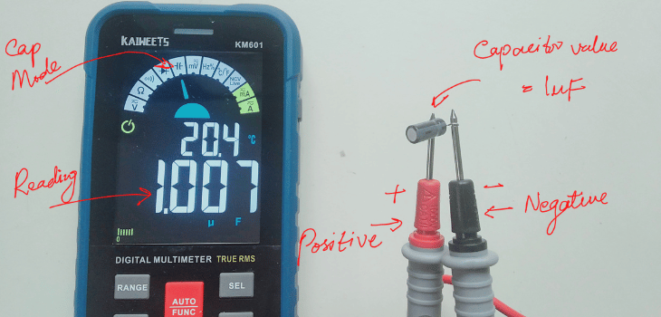
- Compare it with the body written value of the capacitor.
- If they both match you have a good capacitor, else your capacitor is bad.
- Luckily my capacitor in the above picture is a good one 🙂
The value of the meter must match the capacitance written value on its body.
If the meter value differs within 10% the capacitor is good. But if differs by more than 20% then your capacitor is a bad one.
This method is limited to off-circuit capacitors. What if you want to test in-circuit capacitors?
Then for that, we use the following method.
Method 3: By using an ESR meter (In circuit capacitors)
Sometimes a good looking capacitor can be a bad capacitor. Now, to find out such capacitors while they are inside the circuit.
For that, you need to measure its ESR value rather than its capacitance value. To measure the ESR value we need to have a good ESR meter like MESR-100 (Amazon link).
Follow the following steps for this method:
- Turn on your ESR meter
- Discharge your capacitor first and then connect it to the meter.
- Note the ESR value on the tester screen.
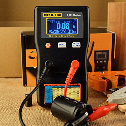
- Compare it to the given values of ESR on the ESR table (yellow printed table on the body).
If the ESR value matches the one given in the table, you have a good capacitor. If the values don’t match you have a bad capacitor that you need to replace immediately.
Also, the above meter tells you on the screen if the capacitor is good or bad as well.
Method 4: Using the M328 component tester
Component testers make electronic component testing easy and fun. You can test a capacitor with the tester with considerable accuracy. Let me show you how I use my m328 tester (Amazon link) for capacitor testing.
Follow the following steps to perform this method:
- Foremost discharge your capacitor, this is very important.
- Turn on the m328 tester
- Put the capacitor in the tester (Don’t worry about the leg’s polarity)
- Press the test button
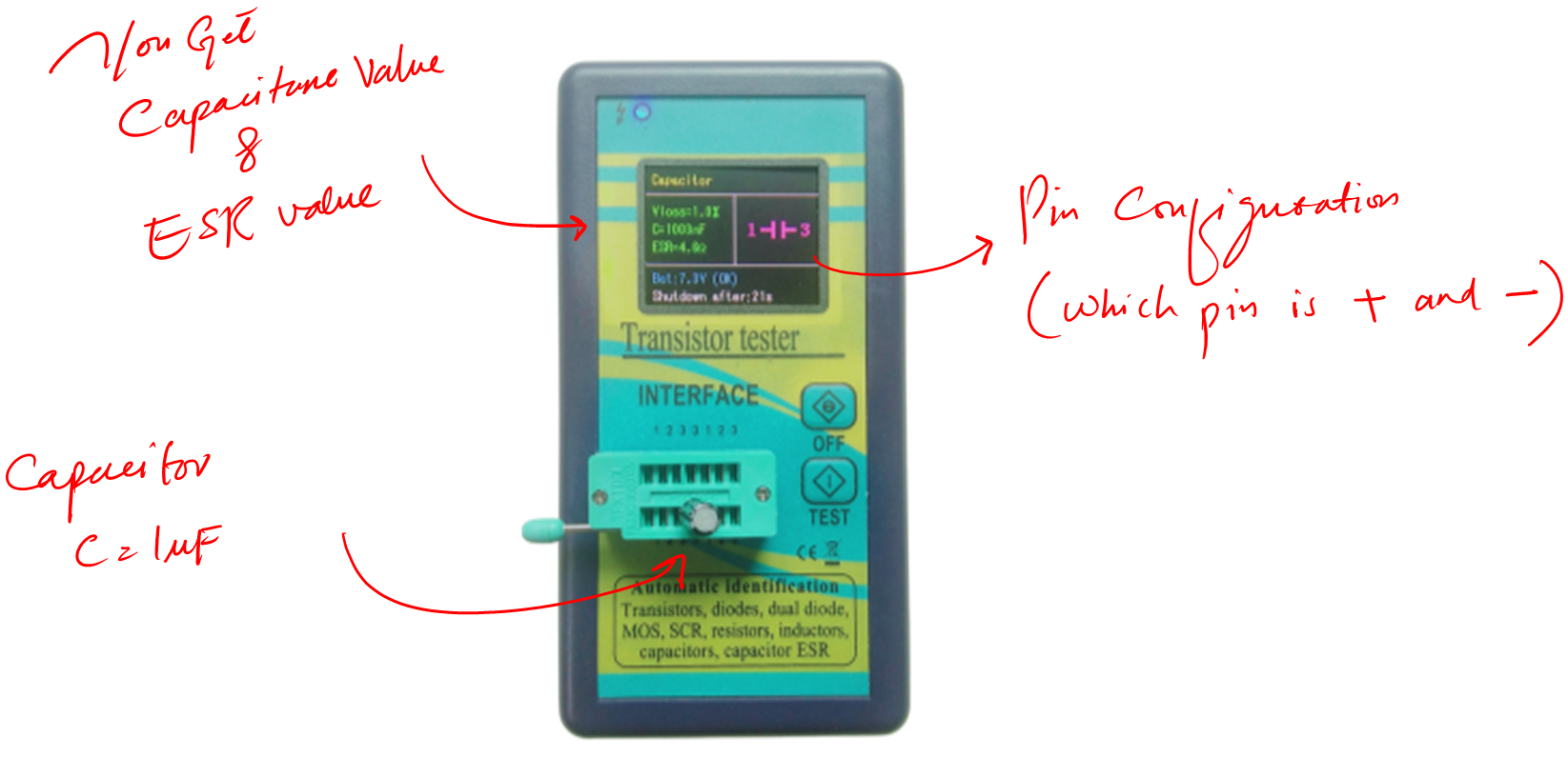
- If the capacitor is ok it will show the results.
- If the capacitor is bad it will show you it is a bad capacitor – it is just that simple.
With this method, you also get the ESR value of the capacitor is as well. Also, you can see which leg is positive and negative with its given circuit symbol.
Remember to always discharge a capacitor before testing it with any device.
What happens is if you discharge the capacitor, it might damage your measuring device by providing high voltages and current flow through it.
3. Diode testing
Let’s talk about another electronic component testing, i.e. diode. You know, the diode is a core part of every power supply. And you can say power supply is a core part of every electronic device.
A diode is a two terminal passive component that when biased in forward conditions allows the flow of current only in one specific direction.
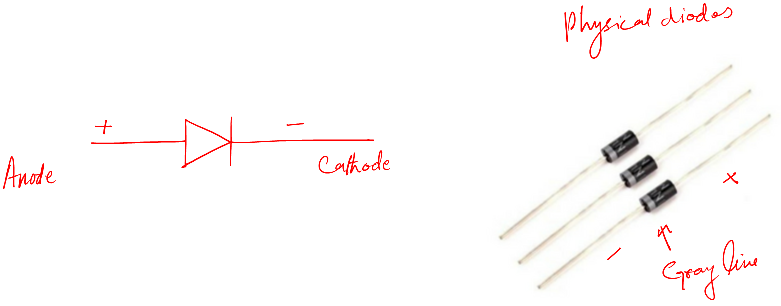
We consider a diode as a digital switch with fast switching, recovery time, and low power consumption.
Let’s see how we test this component.
Method 1: Visual inspection
Guys, I believe now that you know that by visual inspection I mean to look for obvious symptoms.
Usually following are the bad diode symptoms:
- You can clearly see it burnt out – happened because of overcurrent flow.
- It is broken
- There is a small crack
- The color of the body has been changed
- Terminals at the PCB board are turned black – in some cases
- Heats up way too quickly
- There is a noise in the system – if your diode is in the circuit, especially the ripples are increased in power supply output.
Examples of bad diodes.
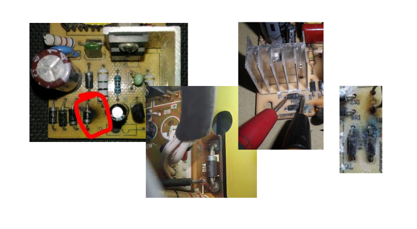
These are not the hard core symptoms. There can be other situations as well.
But I will leave that for your imagination as at the end of the day you are human, and you have that faculty to judge or sense if there is something wrong.
And I am sure you will use that faculty for the cases of diodes as well. By applying the above you can eliminate the very obvious bad diodes.
You will find such cases in rare situations where there is a huge current flow.
Usually, circuits are protected from overcurrent flow. This happens when the manufacturers want to save some costs while keeping the prices low for consumers.
Method 2: Using a multimeter
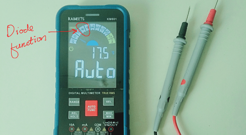
For this method, your digital multimeter must have a diode function. You will find the diode test function in almost every multimeter. So don’t worry at all.
Look for a small diode sign on your multimeter.
Follow the following steps for this method:
- Take your multimeter and set it to the diode test function.
- Take the diode you want to test and connect it to the probes of a multimeter.
- If you see the results on the screen note them down.
- Now reverse the probe connection, and again note the reading on the screen.
Now, your reading should be like this.
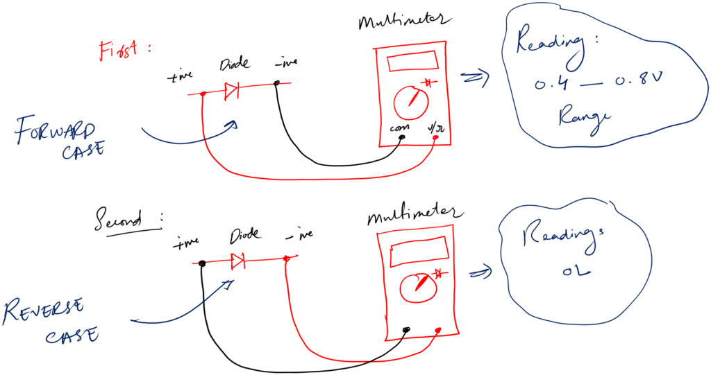
It must be, for one of the two readings, in the range of 0.4V to 0.8V. And it must be OL for the other reading.
If it is as I mentioned above, you have a good diode.
If you get OL for both readings, your diode is bad. Or if you get a reading of around 0.4V for both readings, again you have a bad diode. It is time to replace it.
The good part of this method is, that you can carry it out with in circuit diode as well.
You don’t need to desolder the suspicious diode from the board first, test it, and resolder it again if it is a good one.
You can sense that this method is very practical, efficient, and very time saving especially if you work with a lot of electronic repair boards.
Method 3: Using a component tester
A component tester like m328 Tester makes our life very easy when it comes to testing various electronic components. I use it most of the time.
Follow the following easy step to test any diode:
- Turn on the m328 tester
- Put the diode in the socket of the tester
- Press the test button.
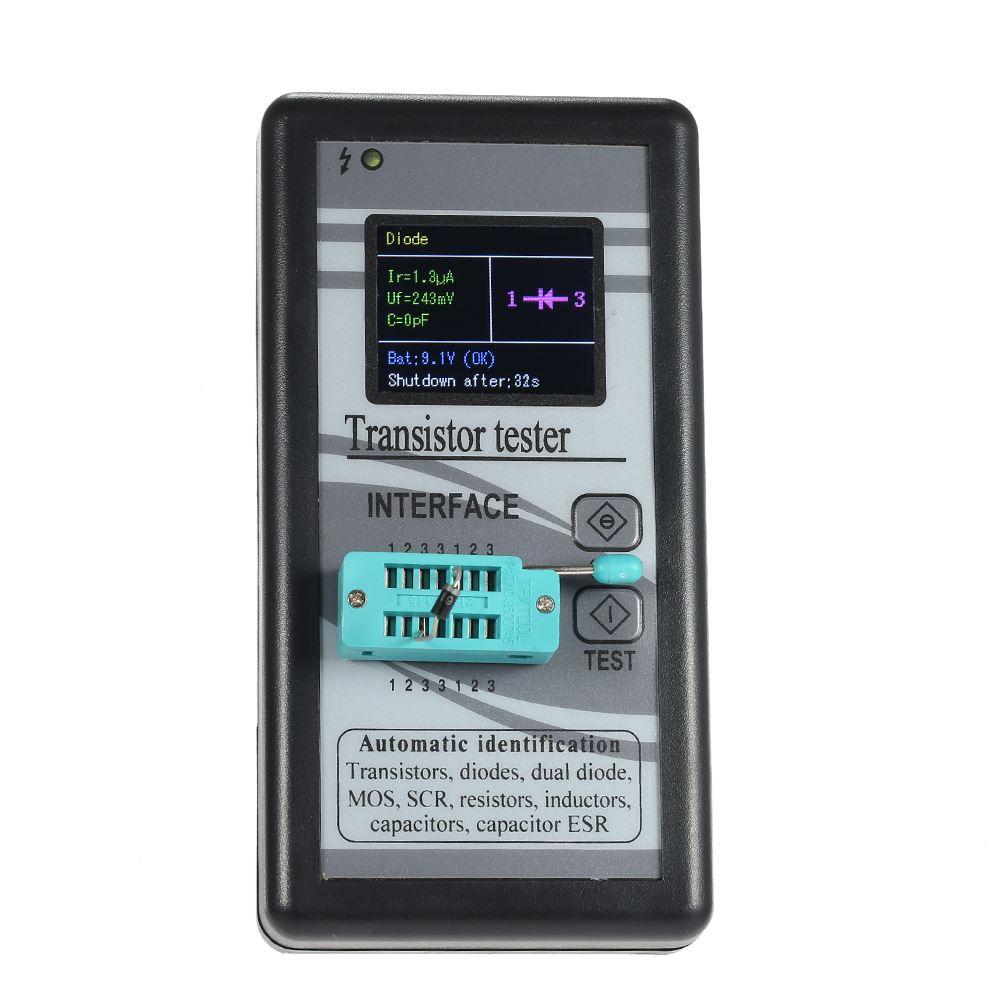
- Now, if the diode is good, the tester will show you its forward voltage meaning that it is a good diode.
- If a diode is bad the tester will show you a message saying, bad component – it can’t be simple than this.
The limitation of this method is, it is not applicable for in circuit diode testing. Though if you are an electronics hobbyist, you can solder probes to the meter and redesign it for in circuit testing as well.
4. LED testing
LED is a special type of diode. It is a two terminal passive component that comes in a variety of colors, shapes, and sizes.
But it is still a diode that emits light upon the application of power.
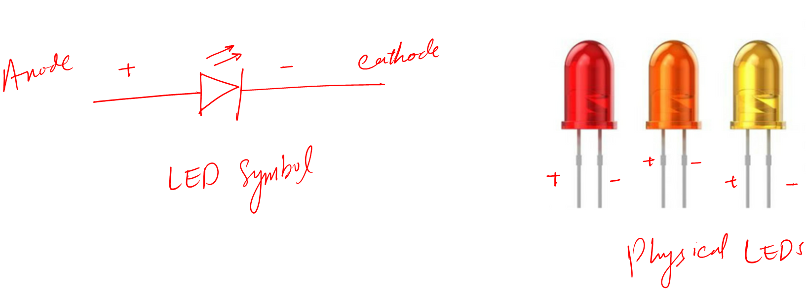
The main use of an LED in a circuit is an indication. We use different color LEDs to represent different states of a circuit or device.
For example, a green LED when turned on means that your device is ON now. If the color is red that means your device is OFF.
All the testing process for testing the LED is the same as I discussed above for the case of the diode.
5. Transistor testing
You know, the transistor is the most powerful single electronic component you will ever see. Because of this guy, we have this modern technological world around us.
Basically, a transistor is a three terminal device that can switch the incoming singles as well as amplify them according to the requirements of our design.
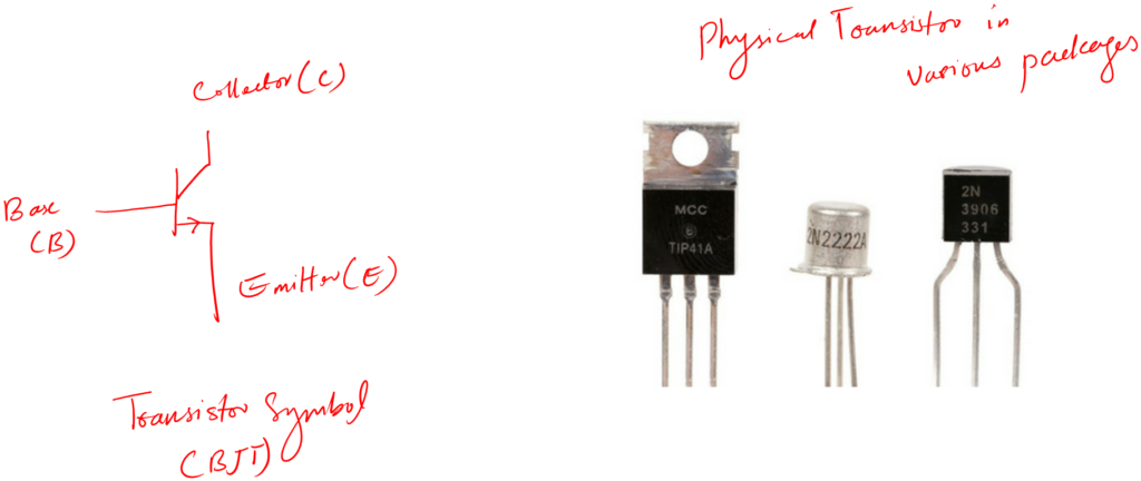
There are several types of transistors specifically designed for required tasks.
For example, there are MOSFETs that are best used for fast switching and high input impedance.
There are BJTs that play a key role in almost every electronic circuit for their reliability and low cost.
Let’s see how we can test transistors.
Method 1: Visual inspection
Transistors (except for power transistors) often do not work at the front end in most applications. For this reason, there is a slight chance of burring a transistor due to overcurrent flow in most circuits.
But the key thing to remember is that: overcurrent is the main cause due to which most electronic components get damaged.
So, if you are using a transistor for some high gain application then there is the chance of overcurrent flow. But if the transistor is not handling such power, chances are those transistors will live for a very long time.
Alright!
Let’s see some signs of a bad transistor that can help you identify a bad transistor right away in any circuit board.
- It will bust – that simple
- There will be cracks on the body
- The color will be changed
- There may be some dark spots on the PCB near it
- Maybe you can smell something bad near the transistor
For the cases of transistors, visual inspection sometimes is not effective.
The reason is what I just shared – they are not in the direct way of high current flow. Remember this is true only for low power transistors, not for power transistors or amplifier transistors with high gain requirements.
Method 2: Using a transistor tester
The visual method helps us identify the obvious bad transistor. But what if a transistor has no such signs, or what if the transistor is degraded (not working to its full abilities). Then we need to test the transistor with a sophisticated transistor tester such as the m328 tester.
Let’s see how to use the m328 transistor tester to check if the transistor is good or bad.
Follow the following steps:
- Turn on the m328 transistor tester
- Put your transistor in it and press the test button.
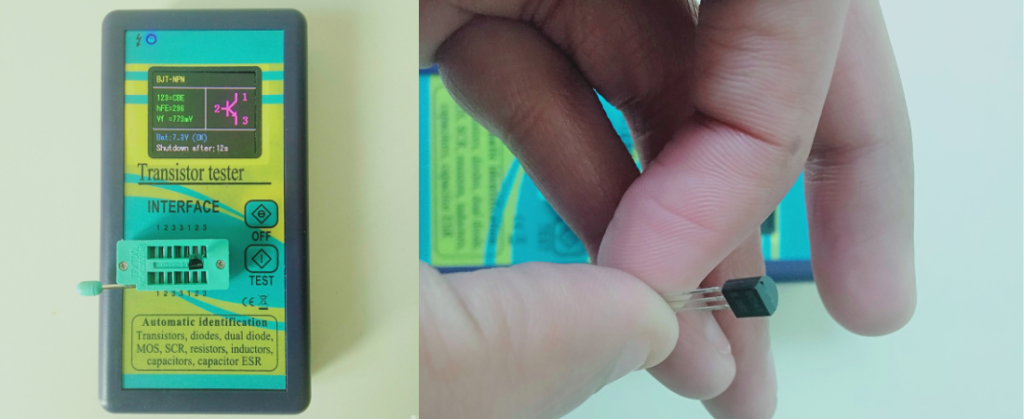
- If the transistor is fine, the tester will show all its required parameters.
- If the transistor is bad, the tester will give you the message saying bad component. That would mean you have a bad transistor.
You can use this method for any off circuit transistor. Don’t worry about the pin configuration. Just plug the transistor in the socket of m328 in any configuration the way you like it.
If your transistor is good, the m328 will show you its pin configuration, DC beta, and much more.
The limitation of this method is you cannot use it for in-circuit testing.
For in circuit testing: you have to first desolder the transistor you want to test. Test it with the m328 tester. If it is good then you have to solder it back on the back. Which is not a really efficient way to do so.
So, if you want to test the transistor inside the circuit you need to have a professional multimeter with component testing options or an advanced-level oscilloscope with component testing options.
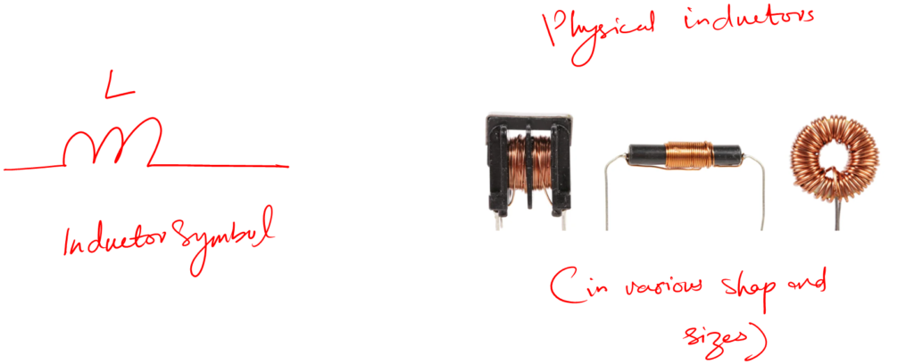
6. Inductor testing
Inductors are not the most used component (except for power supplies). The reason is we want to avoid it as much as possible.
Because they are bulky and sometimes require a large circuit space which is not a very good thing for today’s smart and slim devices.
Inductors are two terminal passive devices that we use for tuning. By tuning, I mean to generate resonance (along with other circuit elements) required for the receiving and aligning with the desired frequency.
For example, radio uses inductors so that we can tune to different frequency radio channels.
Other than tuning, we use an inductor for filtering noise from the incoming signals such as the input main AC.
And this is the reason, so many smart devices have separate chargers. Because chargers have inductor chokes which make them bulky.
Let’s see how we can test an inductor.
Method: Using a component tester
An inductor is no different from the rest of the other components we tested with a component tester.
Follow the following steps to test the inductor by the component tester
- Turn on your m328 tester
- Put the inductor in the socket of the tester (please make sure the inductor is discharged)
- Press the test button
- If your inductor is good, the tester will provide you with the required parameters.
- If your inductor is bad, the tester will let you know so.
Sometimes the inductor will be too big to fit the right way in the m328 socket. In such cases, you have to use connecting cables with your component tester socket.
Again, this method is not suited for in-circuit inductor testing. You have to first desolder your inductor if you want to test it.
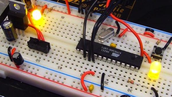
7. Integrated circuits (ICs) testing
Integrated circuits (ICs) are circuits on chips. They are compact and save us a lot of board space.
They are those black rectangular shape boxes (with many legs) that you can see in any electronics circuit.
To test ICs we require an IC tester device. These tester helps us to identify the bad IC.
If the IC is in the board then we can make use of a multimeter as well. However, the limitation of this method is every IC is different. To test in-circuit IC with a multimeter we require to have a working knowledge of each IC.
Conclusion
The process of finding out if the under test electronic component is good or bad is called electronics component testing.
Electronic component testing is very crucial. Because if you don’t test our components before putting them in circuits.
Chances are we might not get the desired outcome. And in the worst case, we can damage our circuits.
It is also important in repairing electronics work where we deal with old boards. Sometimes we have to replace a component, but we are not sure if it is good or bad.
In such scenarios, testing helps us a lot. It saves us money, effort, and most importantly time.
In this article, we look at some methods through which we can test electronic components.
Now, as you know, there are so many electronic components out there. Every component is unique and requires different types of equipment for proper testing.
To tackle this situation, we first look at the general solution that can be applied to almost every component you may encounter in your field life.
These general solutions are:
- Visual inspection
- Using the required electronics test equipment
Then we try to have a detailed discussion on testing all the major components.
There you have it guys. That is all I have to share about electronic components testing. I hope you enjoyed it.
Now, it is your turn. Please share in the comments which method you find interesting. Also, if you have any questions let me in the comment section. Also, I would love your help making this article more useful. You can contact me in person as well.
Share it with your friends, it will help me a lot.
Following are the free resources if you are interested in the detailed process of component testing including the testing mathematics and theory:
- Resistor testing (Know if a resistor is bad, open, or short)
- Diode Testing (Know if the diode is bad, open, or short)
- Transistor testing (Easy step by step guide)
Thank you and have a grateful life.
excellent way of teaching please send me copy, well appreciated
Hi abbas i like your interest also i want share it first for myself then for the others.
Now a time i have an idea before i see your electronics teaching here,with your attention i increased my love to continue electronics maintenance but for time i have problem of money to start because of poor and family. I am government employee. I expect helps from you.
Thank you 🙂
Hello Abbas,
Thanks your information. It is very helpful for me. Do you have contact in email? I have some testing question on the parts onsemi LM324DR2G.
Thanks
Hi, yes there is contact option on the website. 🙂
Thank you so much for the informative knowledge you shared may Lord God bless you always. We pray that your family be guide Lord always,
Thank you for your pray 🙂
Abbas,
Many thanks for taking the time and the trouble to provide this tutorial -appreciated.
May the Almighty aka YHWH give you blessings
Best
Will
Thank you 🙂
i love this,how should i download this?
Thank you. You can print it for free 🙂
I like this idea of technology in electrical and electronics engineering.
Thanks my friend it is a good learning. Thanks again. I will back on you to learn more.