

As a beginner, you will make mistakes while making breadboard circuits – simply called prototypes. It is fine. This is how you learn as a human.
Circuit prototype troubleshooting comes in to help you rectify the problems in the circuits and correct them properly. In the troubleshooting process, we look at the circuit and check its voltages, components, polarity, connecting wires, open circuits, short circuits, and many other things.
As a beginner gets some exposure to different circuits, the ratio of mistakes gets lower and lower. But mistakes are part of the learning journey, even experts sometimes make basic mistakes.
The key is to learn the basics of troubleshooting. In my opinion, in most cases, we are guilty of making fundamental mistakes.
Common beginner mistakes
I think, as humans, we tend to focus on major and most important mistakes and cases. And most of the time don’t put any focus on fundamentals. We somehow mistakenly believe that these are easy basics and that we will never get them wrong.
But,
In most cases, we get the basics wrong.
Following are the basic things or cases that you should always check and master.
Misinterpreting circuit schematics
A circuit schematic is a diagram of a circuit that we use as a guide to build circuit prototypes on a breadboard.
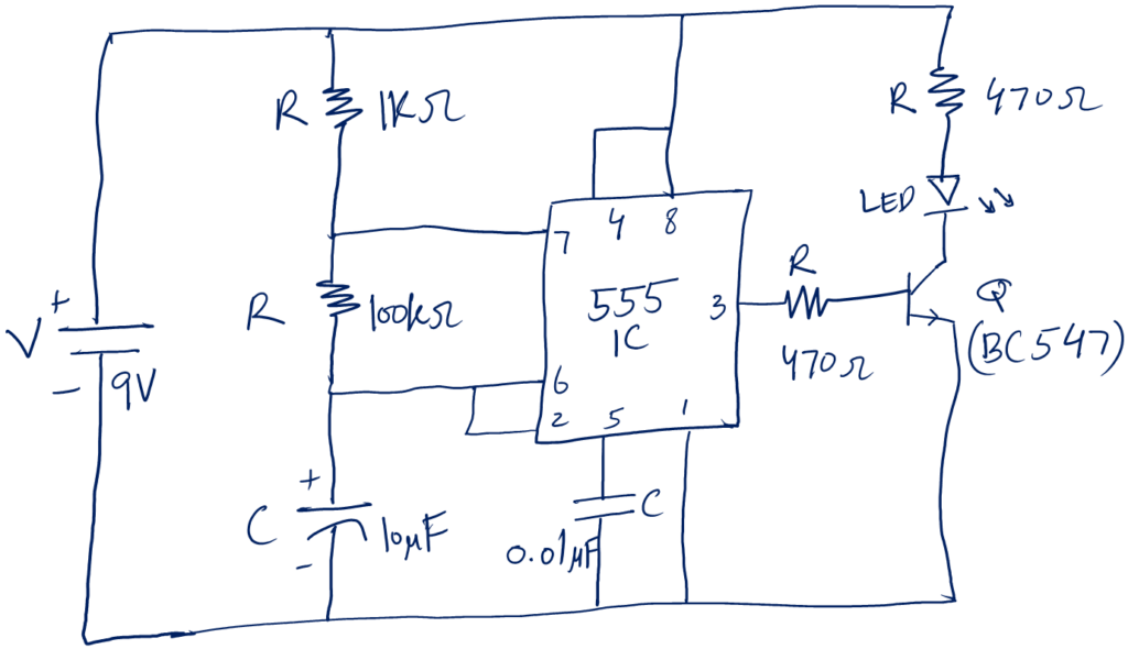
Following is a circuit schematic of LED flashing circuits.
The mistake beginners make is misinterpreting schematics.
For example, the + terminal of 9V is connected to a 1K resistor, the 4 & 8 terminal of 555 IC as well as to the 470 Ohm resistor.
The chance of a mistake is: that the 4 & 8 terminals on physical 555 IC are not located as shown in the schematic. A beginner may confuse the 7 terminal with 4 when making the prototype.
Mistakes of wrong interpretation are very common. My advice is always to understand the schematic first, make the prototype, and double check the connections before powering the circuit.
Use color code for + and – lines. For example, if you use red color wire for the + terminal of the voltage source. It will be easy to track it. Similarly, use black for the – terminal.
Overlooking simple solutions
The next mistake is overlooking the simple solutions, simply by believing that these are simple and wouldn’t work.
This is not a technical mistake. It is more like a mindset problem. I don’t know why it exists and we as humans do it.
But,
I want you to be aware and always go for a simple solution first. If the simple solution doesn’t work, gradually go for more advanced methods.
For example, if the circuit doesn’t work. The first simple solution is to check if you have powered the circuit correctly, then check if the connections are not loose, and check if you have misinterpreted the schematic.
After that, go for little advanced methods like checking the voltage values on different node points.
I hope you got my point. In my experience, it was most of the time a silly mistake like a component was not connected correctly or something like that.
Connection issues
In electronics, a connection means joining two or more terminals of devices in a circuit. Devices can be anything, like different electronic components, terminals of ICs, etc.
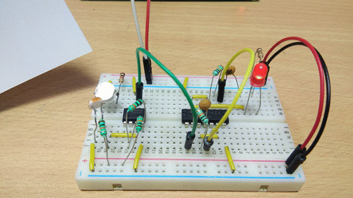
For example, an LED circuit.
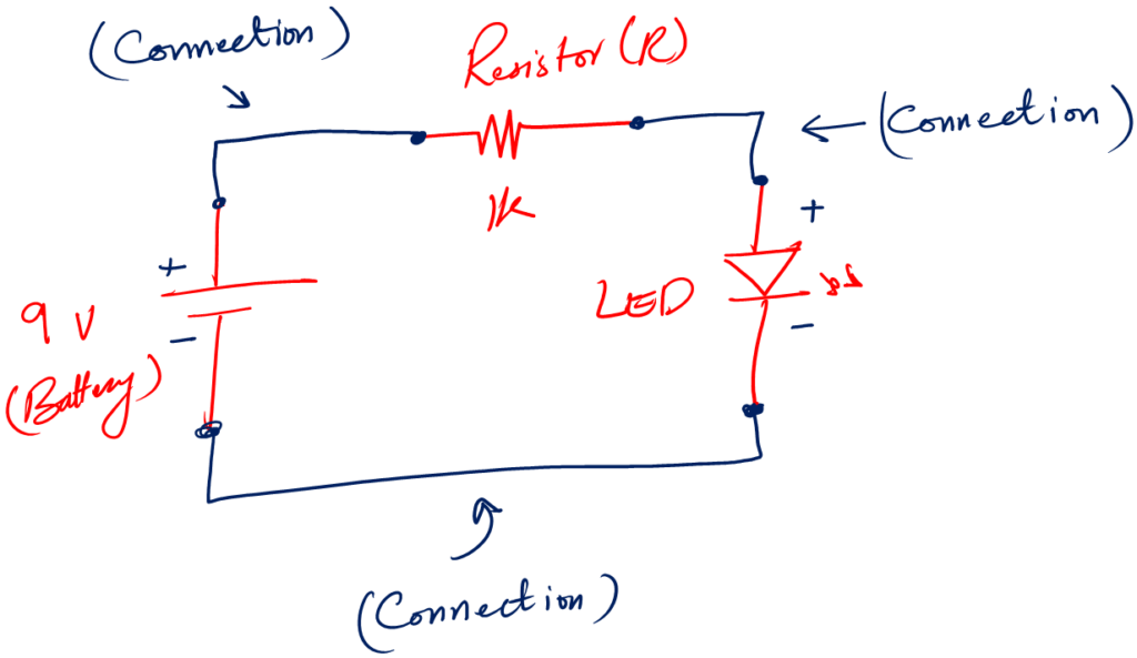
Following is the breadboard prototype of the LED circuit schematic.
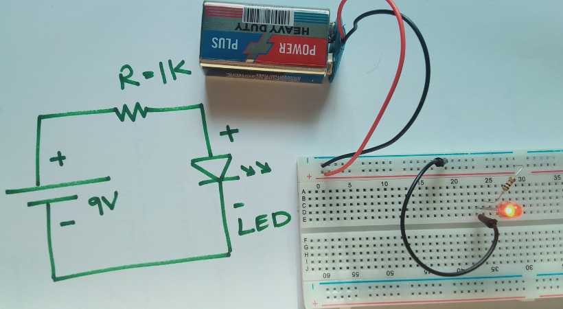
You see, in the physical circuit, the lines of the schematic are equivalent to wires on a breadboard.
This example is simple. The circuit can be more complex depending on what you are building.
Now, using the common sense, what can go wrong with connections?
Think about it.
- You can make a wrong connection, misinterpreting the circuit schematic
- The connection can be loose, it is not properly connected in the hole of the breadboard.
- The connection can be short
In the comment section, please share what you think can go wrong with connections.
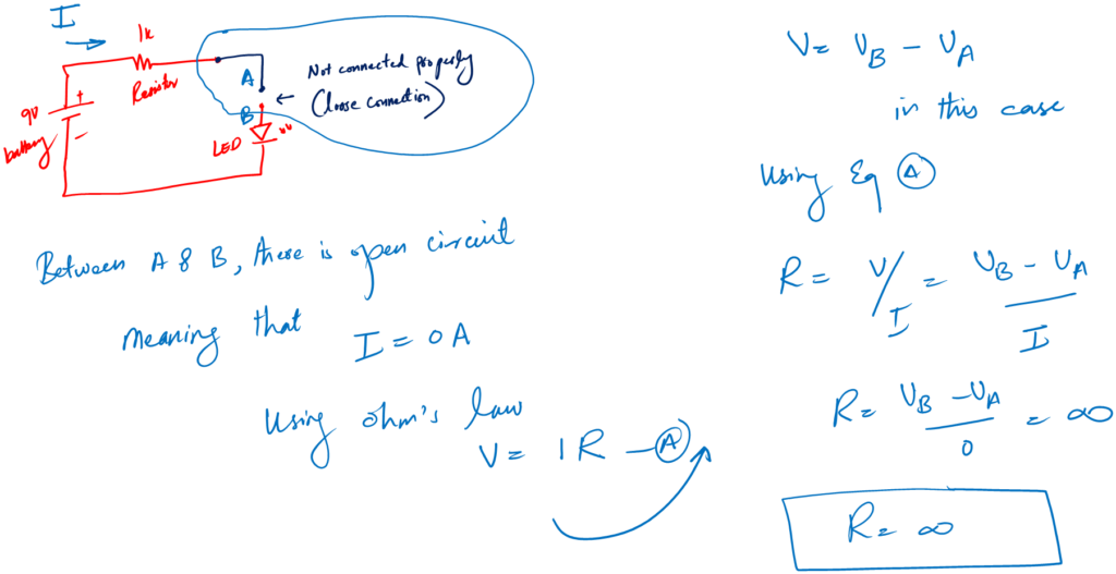
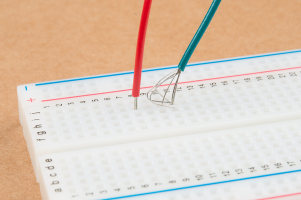
Loose connections
The first problem is loose (open) connections. In this case, the connecting wires or the terminal of a component are not connected properly in the holes of the breadboard.
What happens when there is loose connection?
Well, no current is flowing, so there is no proper working circuit. As there is an open circuit or incomplete circuit.
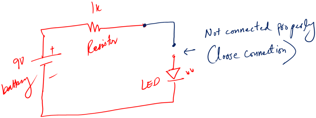
Loose connections make an open circuit, meaning there is infinite resistance and no current can flow.
The following are optional mathematics for a beginner. It is not compulsory, but you should know it.
What causes a loose connection?
- Human errors
- The holes of the breadboard are wide and the gauge of connecting wire or terminal of components is small
- This means that the thickness of the wires or the terminals of components do not match the hole size of the breadboard
- Misplacement of components in rows and columns on the breadboard.
- Not properly inserting the wires in the holes of the breadboard
Troubleshooting a loose connection:
You can find a loose connection simply by gently shaking or wiggling the connection. And you will easily identify a loose connection.
Also, you can find it by looking at columns and rows.
Solution:
- Be careful and gentle with wires and components
- Use standard 2.54 mm hole size breadboard
- Ensuring that the stripped ends of wires are not too long or too short to make a solid connection
- Re-inserting wires and components firmly
- Using wires of appropriate thickness
Just a personal tip, when buying a breadboard, bring the connecting wires with you. Test the wires if they fit the holes nicely and firmly.
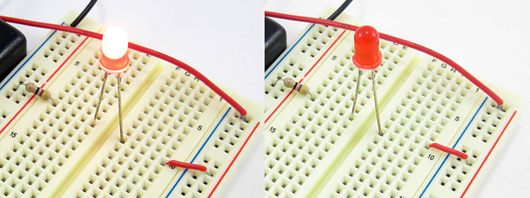
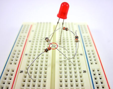
Short connections
The opposite of a loose or open connection is a short connection. In this case, an unnecessary connection has been made. This connection can be between terminals of the same or different components.
A short circuit occurs when two points in the circuit that shouldn’t be connected directly are accidentally connected. It is very harmful. As it can damage the component by overheating it.
What causes a short connection?
- This can happen due to overlapping wires or components placed too close together.
- Misinterpreting the schematic
- Not cleanly making the circuit. For example, placing the component everywhere you like and don’t plan the overall look and cleanness. At the end getting a messy circuit.
- Connecting the legs of the same component in the same columns of breadboard.
Troubleshooting a short connection?
The big sign is that a short component or connection starts to overheat quickly. If you face such a problem, immediately remove the power source from the circuit.
See if the component is not connected to the same column. Because a column is short: it makes the component short circuit too.
Solution:
- Double check the circuit schematic and connection on the breadboard.
- In case of short, the first thing is to remove the power source.
- If the circuit has an integrated circuit (IC) make sure the IC is placed properly, i.e., on the centroide of the breadboard.
Personal tip: Keep the circuit clean and power the circuit only when you are sure.
Component issues
Let’s focus on component issues that a beginner may face when trying to make circuit prototypes on breadboard.
We know, that a circuit is made of various electronic components. If we don’t know how to work with these components, chances are we may end up burning them.
The following is a circuit:
What can go wrong with this circuit, keeping the components in mind?
Think about it.
Well,
- The component can be faulty: which means it is bad and not working.
- You have misplaced the component on the breadboard
- You misinterpret the circuit schematic
- You don’t know about the polarity of certain components like capacitors and diodes.
- You don’t know how to measure components correctly. And placed the wrong value component on the breadboard.
Maybe I have missed some points here. The point is, that it is our lack of information that leads to component issues.
Faulty component
This is very straightforward. You put a bad component in the circuit intentionally or unintentionally. The circuit won’t work — it is that simple. In some cases, you may damage the other connected component as well by overloading.
The best practice is never to use a faulty component.
Now, the question is how to troubleshoot a faulty component.
First, look at the component before putting it in the circuit. A faulty component can be spotted very easily by the eyes. It is busted open, has cracks, or some bad smell.
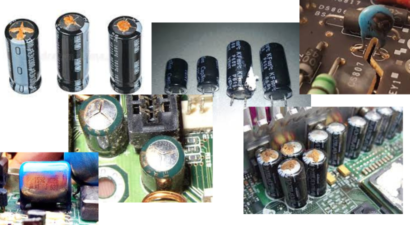
This strategy is good. Like filtering out a bad component before doing anything. This is the visual inspection.
Visual inspection is not effective, I mean it is not enough. We must make sure that we use a good component in our circuit.
To do so, we do component testing. We test every electronic component for the using using various tools like a multimeter.
Now,
If the component seems ok on the outer side, and when you make the circuit. The circuit doesn’t work. What to do in such cases.
Well,
A faulty component most of the time gets heated. So if you have a component that is heating up, chances are it is a faulty one.
Component polarities
Polarity means that the component has to be used in a specific orientation, or it will not operate.
For example, an electrolytic capacitor has polarity. Which means it has positive and negative terminals.
If you don’t connect the positive terminal to the positive of the voltage source and the negative to the negative, the capacitor will not work. In some cases, it may start to heat up.
Always, look for the polarity of components. Following are some polarity defended components.
- Electrolytic capacitors
- Diodes
- LEDs
- Transistors
You can find out about the polarity of every component using its datasheet. A Datasheet is a documentation for a component about it dimension, ratings, and polarity.
Power supply and voltage issues
A power supply is an important device for prototyping. It helps us power the circuit.
There are so many power supplies to work with. For example, you can use batteries, a benchtop power supply, and USB power.
It doesn’t matter at the beginner stage how smooth the waveform of your voltage source is. But make sure it is not noisy.
I always prefer the following breadboard power supply for beginners. It is a USB powered voltage source designed for breadboard prototyping.
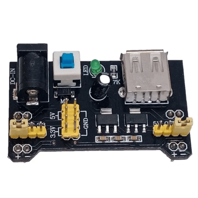
It is safe and has 5 and 3.3 DC voltage values. These values are enough for all beginner projects.
The mistakes beginners make with power supplies are:
- They connect the wrong voltage value without properly measuring them
- Sometimes connect the voltage source in reverse — which can be very dangerous
- Working on circuits with power on.
- Applying too much voltage or current, results in overloading and damaging the circuit parts.
I want you to be very careful with these mistakes.
Incorrect voltage
If the circuit requires 5V and the maximum it can handle is 9V. You apply 12V to the circuit.
What do you think would happen?
Chances are you may damage the circuit by overvoltage. So, never do this. 😀 Always apply the voltage within the required limits. Low value voltage may not harm your circuit, the circuit just won’t work properly. However high voltages can burn the circuit components.
Battery issues
If you are using dry cell batteries for your projects. Make sure you are using the correct voltage values. A standard voltage of 9V is enough for most of the projects.
Remember, with use the battery discharges.
The mistake beginners make is: they don’t monitor their batteries.
They connect the discharged batteries. The circuit barely works, and they think there is some issue with the circuit. Ignoring the fact, maybe it is the batteries that need to be replaced.
Complex Circuits troubleshooting
When you start working with circuits that have a lot of components. We call such circuits complex circuits. Troubleshooting methods remain the same but the overall strategy is changed.
We still look for schematic misinterpretation, loose connections, or faulty components. But as the circuit is complex we need a step by step approach.
Step by step approach
In this troubleshooting process, we start with the power supply and test every section of the circuit up to the output or the last section.
This method ensures that we test each wire, each connection, and each component throughout the circuit.
If the circuit has separate working areas. A circuit has a power supply, amplifier section, filtering section, and other such sections. We divide the circuit into separate blocks. We test each block.
Use of multimeter
A multimeter is an electronic tools that help us measure:
- Voltages
- Current
- Resistance
- Continuity
- Capacitance
We use a multimeter in circuit troubleshooting as well. For example, if we are not sure if the wire is connected properly, we use the multimeter continuity function to ensure that.
In small circuits, we rarely need a multimeter. But for debugging complex circuits, it is must have tool.
Besides the multimeter, we also need an oscilloscope and sometimes a function generator to ensure a proper working circuit.
Learning from troubleshooting
If you make a mistake and don’t learn from it. I think it is not good.
Why?
Because some of these mistakes will have a collection of damaged components, not working circuits, frustration, anger at the circuit, and so much more.
If you don’t learn from those mistakes, they may repeat. Chances are it will demotivate you and may start to believe, that electronics is not for you.
So, how to properly learn from those mistakes?
In my opinion, you document them and continue learning.
Documentation for future work
You know, circuit documentation is one of the most important skills a beginner can develop. We make mistakes, but if we document them. We can always refer back and see the solution in the documentation.
This is a very boring task to do, I know.
But it is worth the time and effort. Just have a notebook and start writing the progress of your work. Note down, where the circuit went wrong and what was the effective solution.
Continue learning and making mistakes
Learning always involves making mistakes. Are mistakes fun? No 😀 But this is how we learn.
Please don’t be discouraged by mistakes. It will be frustrating and you may get angry or sad. I want you to know, it is fine. I did it, every great master did it.
Continue learning and I encourage you to make mistakes.
Conclusion
Making a circuit on a breadboard can be tricky for beginners. They may make some mistakes due to which the circuit may not work.
How to handle those mistakes?
Well, we analyze and handle those mistakes by careful circuit troubleshooting.
Electronics circuit troubleshooting is a process using which we rectify the problems in the circuit prototype and correct them.
Usually following are the mistakes one can make on a breadboard.
- Loose connection
- Short connections
- Loose components
- Faulty components
- Circuit schematic misinterpreting
Apart from these mistakes, sometimes we overlook the very basics. For example, voltage reverse connection and discharged battery usage.
Troubleshooting a simple circuit is easy. But when we work with a complex circuit with a lot of components. Then we use the following approaches to handle it:
- We break the circuit into small sections and check each section individually.
- We use multimeters, oscilloscopes, and function generators as well.
- We start from the power supply and go up to the last portion of the circuit.
- This way we ensure we check every wire, connection, and component.
Circuit troubleshooting is an amazing skill. You will make mistakes at the beginning of making circuit prototypes on a breadboard.
It is fine.
But please learn from those mistakes, and document them so that you can use the documentation for fire work.
I hope you enjoyed this article.
Share your thoughts and questions in the comment section.
Thank you & I see you around.
**If you are a beginner, here is a guide to get started with basics of electronics.