

Electronics Circuit Prototyping & it’s Important (Guide, 2026)
A complete beginner or hobbyist may want to convert a circuit schematic into a physical circuit/project, the solution is circuit prototyping.
Circuit prototyping is a process in which we make our physical circuit on a solderless breadboard from a circuit schematic or verify our simulation circuits and their results with a real time circuit. It helps identify design flaws, optimize performance, and ensure reliability before production.
In the rest of this article, I will try to explain in detail what is circuit prototyping and why it is so important.
What is circuit prototyping
If we look back in history. The concept of circuit prototype was introduced in the almost early 1920s.
People use wooden boards and nail components on those boards. Connections were made of copper wires and the overall look of the circuit wasn’t that impressive at that time.
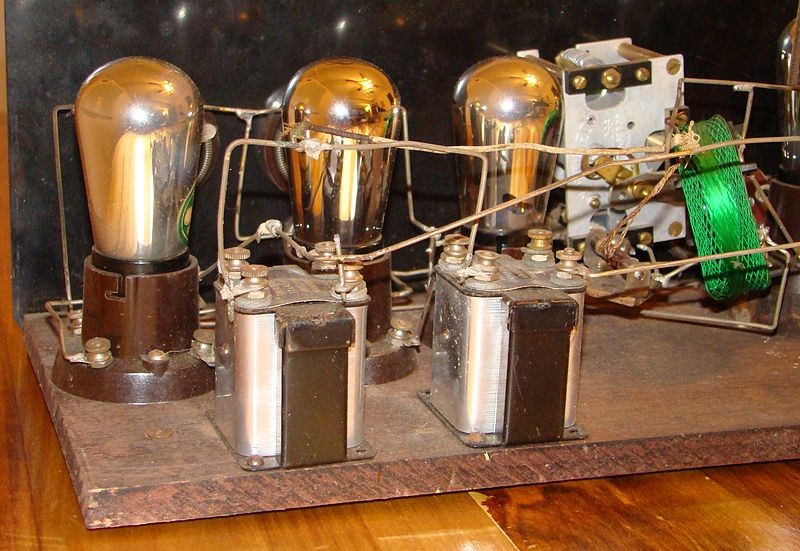
But as the frequency of circuits increased and transistors were introduced those wooden boards were replaced by aluminum board and then later we got today’s version of the solderless breadboard (which we will see soon).
So what exactly is a circuit prototype?
Well, to exactly understand this concept we first need to understand the whole modern process briefly from getting a project idea to the final manufacturing of the product.
The process is really simple.
- First, you have an idea for making an electronic device. If you are a student consider it as your project idea for your semester or final year project. If you are a beginner or hobbyist, consider a circuit diagram of the DIY project.
- Second, you design a simulation for that project. (you can use Proteus, Multisim simulation software for this purpose.). A beginner should not be worried about this step, as he has already a good circuit schematic.
- Third, you test that simulation circuit on a solderless breadboard. This is part of our interest – this stage is referred to as the circuit prototyping phase.
- Fourth, you design a PCB for the project. Then you create a PCB prototype. (The best software for this task is Altium Designer)
- Fifth, if everything is up to the requirements, and you get the results from the prototype that you intended, then it is time for batch manufacturing. If this project was intended for commercial use then it is time to get it into the target market.
Now that we have a brief overview of how an electronics circuit manufacturing looks like. I can now say that:
Circuit Prototyping is the process through which we build, test, verify, analyze, and compare a real time circuit version (build on a solderless breadboard) to the simulation version of that circuit. And see the results from a practical viewpoint.
Or in simple most words,
Circuit prototyping is converting a circuit diagram into a physical circuit – it is that simple.
Following is the example of a circuit prototype on a breadboard:
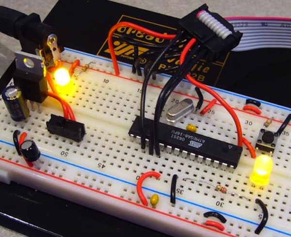
You can see in the above picture that a breadboard (white dotted structure) is a primary thing to consider when making a circuit prototype. It holds and connects all the required components to make a complete circuit.
Why circuit prototyping is important (Applications)
I think at this point you may have some idea why the circuit prototype is important. But there are more interesting applications to it. Let’s talk about those in the following:
1- Solderless approach
In circuit prototyping, we use breadboard which is a solderless device. This makes us able to make a temporary circuit without permanently soldering the components together.
2- Easy to make changes (compensating errors)
If you are a student, chances are you will make some mistakes. You may connect a component in the wrong way, and maybe you completely put a component, especially ICs wrong.
A circuit prototype can compensate for all these errors. But it doesn’t mean you should not be careful. Sometimes if you wrongly connect a component you can damage that component.
3- Reusability
It is not always guaranteed that on your first try, you will get your desired results. You may go through different iterations and variations. Thus, it is required to have reusability of your resources.
Luckily, with circuit prototyping, we have the advantage of reusability of all the components, ICs, wires, etc. Also, you can use the same components for completely different projects saving you a lot of resources and money.
4- Testing
Circuit prototype gives you the ability to test your circuit the way you want it. You can test the circuit in real time environment to ensure that it will behave the same if you go for a final PCB version.
5- Analyzing & Verification
By analyzing & verification I mean to see for various node voltages and see if they are what they are supposed to be. Also, to check various components if they are working correctly.
Tools for circuit prototyping
For circuit prototyping, you need to have some basic electronic devices and hand tools. Follow are some fundamental things you should invest in if you want to make a career in electronics.
1- Solderless breadboard
A solderless breadboard is a tool we use all the time when making any circuit. It is like a go-to tool when it comes to building physical circuits.
Remember, we use a breadboard to make circuits, but these circuits are prototypes.
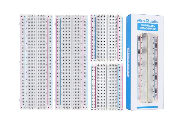
Every breadboard has rows and columns. We put our components in these rows and columns, depending on our design.
Also, we connect various components through connecting wires. In the end, we have a working prototype of a circuit (if everything goes the precise way it is supposed to be).
The following resource can further help to know more about breadboards:
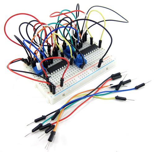
2- Connecting wires
As the name explains itself effectively. Connecting wires are copper wires that help us connect various electronic components in the required manner to build circuits.
Connecting wires come in various shapes, sizes, and lengths. But they all serve the main above application.
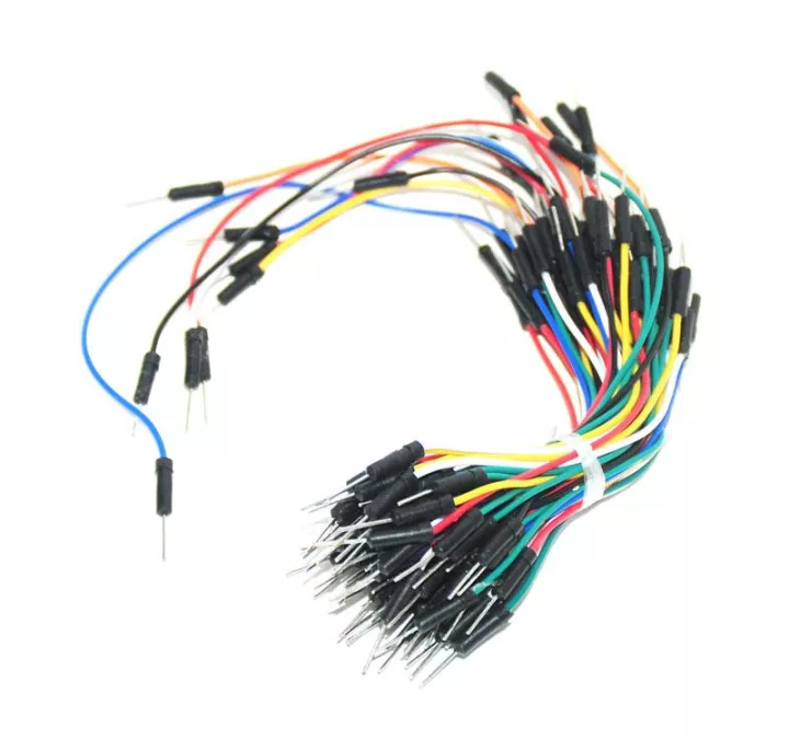
Some people also call it jumper wires, but I don’t like this term. It creates in my mind an image of a jumping wire in a circuit. Who wants such a dancing circuit? Anyway, jumper wire is the most used term, so I have to stick with it.
The above wires are perfect for working with a breadboard. But it is not necessary that you have to use them in every circuit.
Working with the above jumper wires, you will end circuit may look like the below:
Which is good, but we can make it a little better looking. Instead, by using the above jumper wires, we can use the following jumper wires.
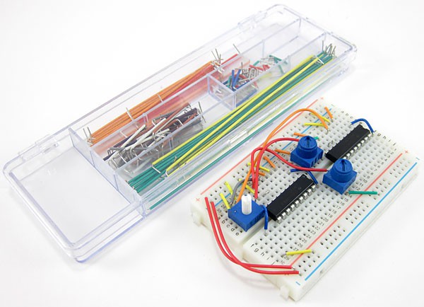
You can tell the difference yourself.
It is the same circuit, but it is not messy and looks more professional than the above one.
Remember, no matter which connecting wire you use, it does not affect the output of the prototype circuit.
Now, the first discussed jumper wires come with fixed length and fixed open terminals. However, the latter discussed ones don’t come that way. You have to cut them according to your situation. To properly handle these wires, you need a proper wires tool kit, as discussed below.
3- Wires tool kit
By now, you should know why we require a wires tool kit. You know, when I was a student, I didn’t have a lot of money.
I bought only a wire cutter and a wire stripper. These two tools just work fine for almost all of my work.
So, if you are a student or beginner, I would say you only require these two basic tools. But if you can afford it, why not have fun with amazing tools and gadgets?
You should have the following few simple hand tools available:
- A pair of small wire cutters, often also called diagonal cutters to cut wires and components leads to length
- A small pair of long-nose pliers to bend and shape wires and leads
- A pair of wire strippers to remove the insulation from the ends of jumper wires
- A small screwdriver to adjust potentiometers and such
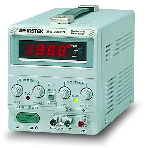
4- Power supply
The power supply may not be directly influencing your circuit prototyping but with it, you cannot complete the whole process of prototyping.
No matter what type of circuit or project you work on. You need a power source to power them up.
Power supply just helps us achieve the above efficiently and safely.
You can consider a power supply as an energy supply source for our electronics prototype projects and circuits. Without energy there will be no working circuits, that’s simple.
And that is why a decent power supply is a must have tool, device, or equipment for an electronics guy’s work environment.
Now, if we talk a little technical here. I hope you won’t mind.
The main voltages coming to our houses are alternation (you can say main AC voltage, only for your simple understanding) with an amplitude of 220Vrms or 110Vrms, depending on which part of the world you are living.
Most electronics are DC. So you need to convert that coming AC to DC to properly power up your electronic devices.
That is why we need to have a power supply – a simple middleman that takes on the main AC as input and converts it into DC at the output.
5- Multimeter
In the circuit prototyping process, you will be handling a lot of electronic components, and you must correctly measure them before putting them into your circuit. So you need a measuring device called the multimeter.
A multimeter is a basic electronics device that helps us measure:
- Resistance of resistors
- Capacitance of capacitors
- Inductance
- Continuity of a wire, PCB trace, and circuits
- Alternating voltages & currents
- Direct voltages & currents
- and much more
We also use a multimeter to troubleshoot an electronic component or a complete electronic circuit.
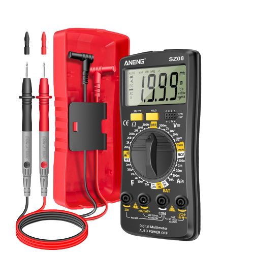
You know, a multimeter is very fundamental, and you just cannot go with electronics prototyping without having a decent multimeter.
And if you ask me, I just like to have a bunch of multimeters 🙂
But if you are getting started with electronics, and you are not working with main AC voltages (i.e. 220Vrms or 110Vrms) then you can have any low price tag multimeter as long as it is working.
Concepts required for prototyping
To be good at circuit prototyping a beginners should first understand the following concepts. They are the basic concepts of prototyping.
- What is a circuit schematic
- Circuit components symbols
- Reading a circuit schematic
Let’s start with the circuit schematic.
Circuit schematic
It is a graphical representation of a circuit. You can think of it as a map of a circuit. Following is an example of a circuit schematic.
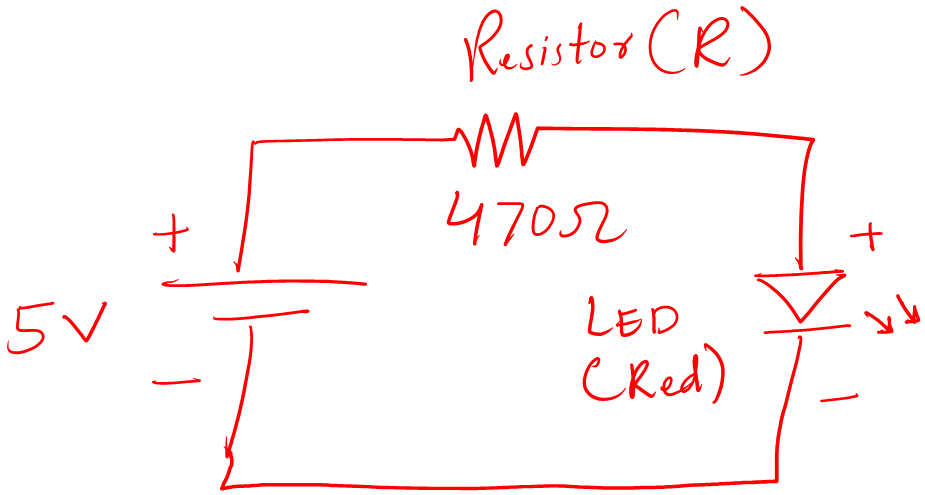
This schematic represents an LED circuit.
Now, the circuit schematic may be as simple as the above and can be complex as well. Also, remember circuit schematic is also called a circuit diagram. Both terms mean the same.
Circuit component symbols
You can tell that a circuit schematic has a bunch of different symbols. For example, you can see in the below schematic.
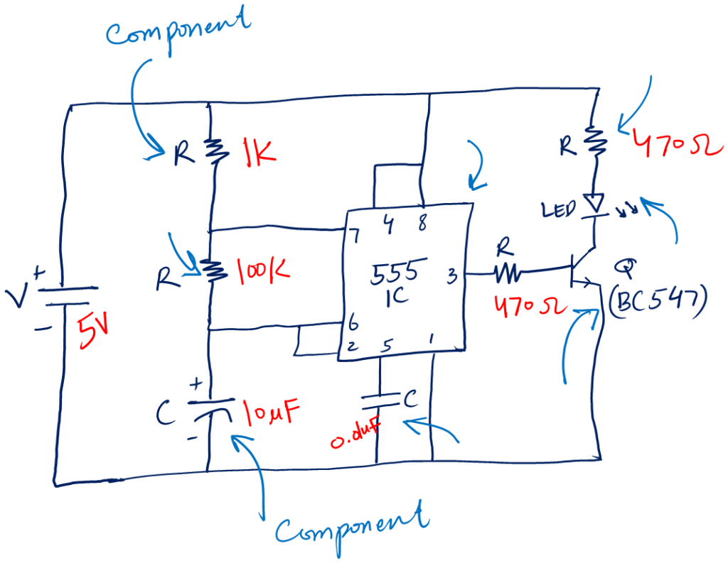
The symbols represent different circuit components. To be good at prototyping it is a must to first understand electronics components (resistor, capacitor, transistor) symbols as well as all the circuit symbols (voltage, current, fuse, etc).
The following are the fundamental symbols for a beginner:
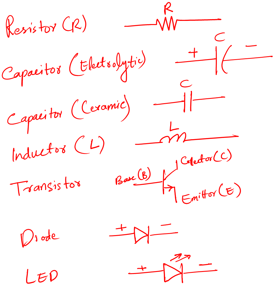
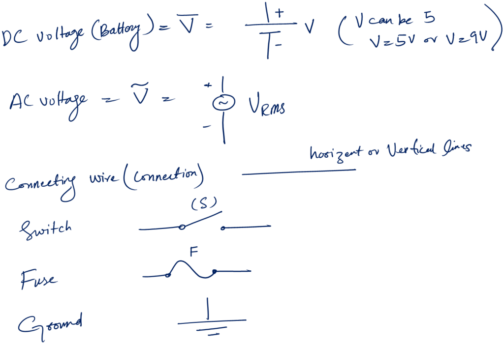
I hope you are not scared by these symbols 😀 I promise electronics is fun.
Circuit schematic reading
By now you can tell that a circuit schematic is a graphical representation and to read it properly one must understand the various circuit symbols.
Reading a schematic is simple, you start from the positive terminal of the voltage source follow all the connecting wires from there, and end on the negative terminal of the voltage source.
You properly look around which wire is connecting to which component.
LED circuit prototyping (Example)
To better understand prototyping let’s work on an example circuit. The circuit is an LED circuit which is very good for beginners.
Step 1: Understanding the schematic
Following is the circuit diagram for an LED circuit.
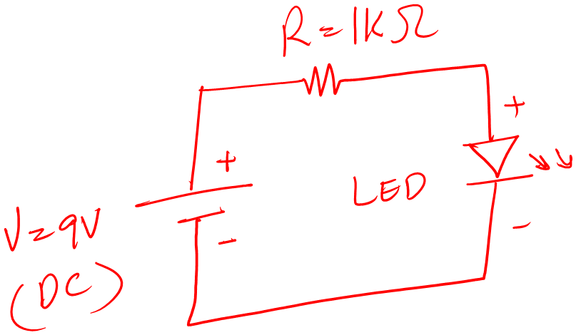
You can see that there are three circuit components.
- 9V battery
- 1K Resistor
- LED
The positive terminal of the voltage source is connected to one of the resistor legs. The other leg of the resistor is connected to the positive leg of the LED. The other leg of the LED, the negative one, is connected back to the negative terminal of the 9V voltage source.
All the components make a series circuit. Which means the same amount of current will flow through the resistor and LED.
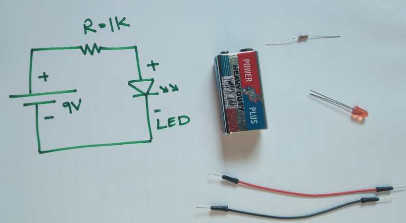
Step 2: Component preparation
For the above LED circuit schematic, we need the following:
- 9V Battery
- 1K Resistor (1x)
- LED (1x)
- Connecting wires
- Breadboard
- Multimeter
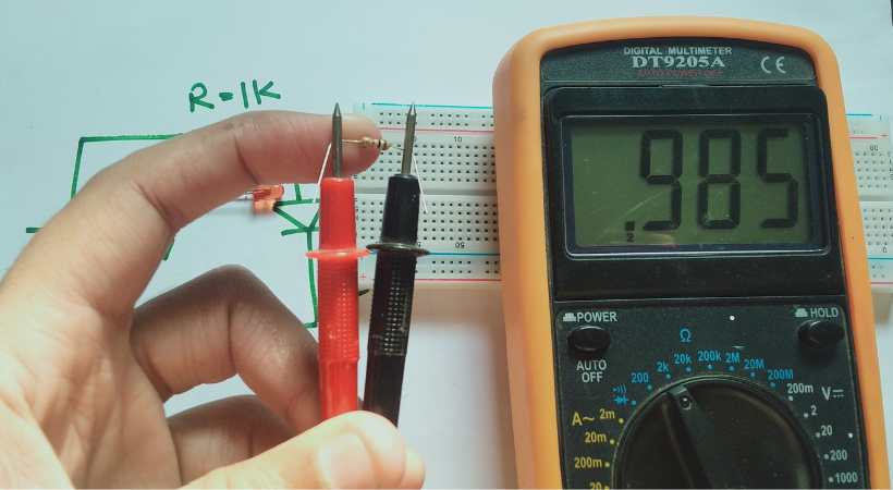
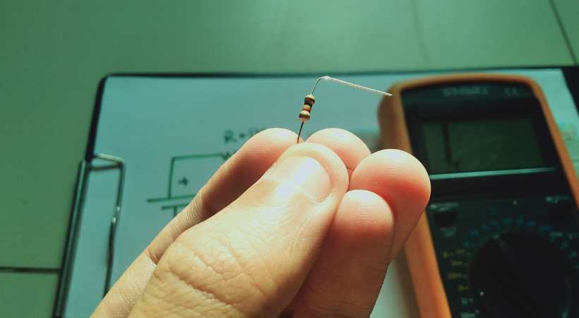
Measure the resistor value by using the multimeter to ensure we are using the correct resistor.
Also, test the LED to ensure it is good and working.
In this case, we have a simple circuit. However, the testing and measuring of the components are the same for complex circuits as well. We must ensure that we are working with correct and good components.
The following resources help get started with electronics measurements and testing.
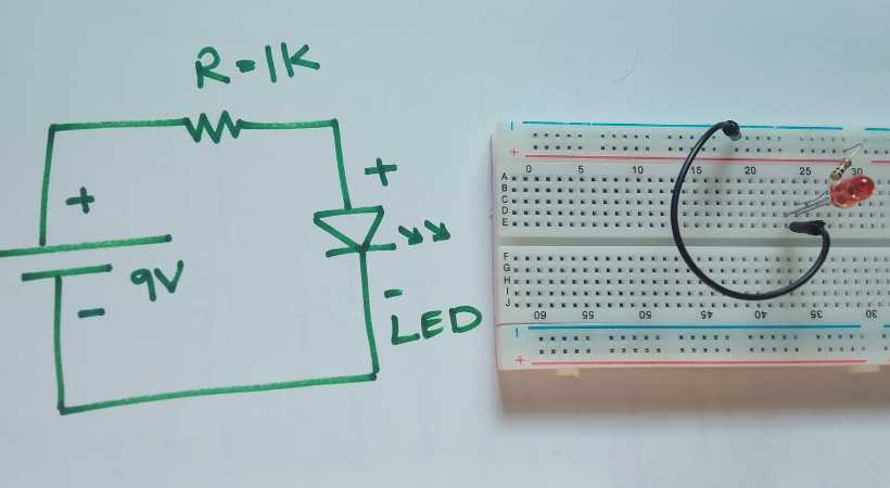
Step 3: Make the circuit on a breadboard
After we make sure everything is good. It is the time to connect the components as directed by the circuit schematic.
A good practice is to draw the circuit on paper by hand. This helps remember the connection and reduces the chances of missing connections. But you can print it as well.
For the resistor bind the legs by 90 angle so that they fit the breadboard nicely.
Make the circuit.
Make connections according to the diagram. Be careful. After making connections don’t power the circuit immediately.
Double check the connection.
Now connect the power source. Are you excited?
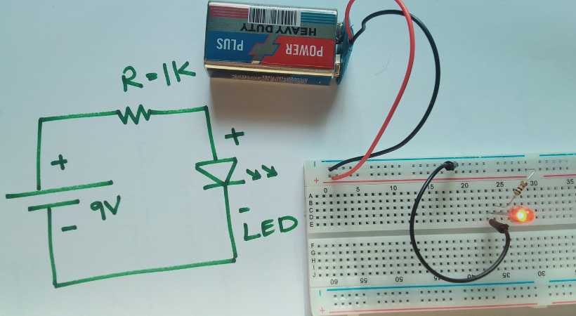
For some of you, it may be your first electronic circuit. For me, it was my first circuit. It always excites me and brings back some old memories as well.
Troubleshooting
Making circuits is not that easy for beginners. They may make mistakes, and that is ok.
But the question is how to handle those mistakes. This is called troubleshooting. Troubleshooting is the process of finding the causes of why the circuit is not working the right way.
Now there can be many reasons a circuit may not work. That is why we have a dedicated section of circuit troubleshooting to tackle all the possible cases.
Follwoing is a brief overview of common mistakes:
- Wrong circuit schematic reading.
- Making wrong connections
- Loose components
- Wrong component polarity
- Short circuit
- Shorting the legs of components
- Open circuits
- Overloading
- Not caring for the cleanness and making a messy circuit
Above are the common mistakes. Don’t worry if you make them in the beginning. I did them and I think it is how we humans learn things. It is not fun to make these mistakes, to be honest, but it’s worth it.
Safety
Prototyping involves powering up the circuits. Many of the circuits are low power for beginners (9V Battery is used). But it is not always the case. Some circuits may require more power and you may deal with high voltages including both AC and DC.
The best practice is,
- Never work with a circuit when power is on.
- Never rearrange the components when the circuit is attached to a power source
- Always look for component ratings. Never operate a component beyond its rating.
- Avoid any short circuits in the prototype.
- Always use insulated tools like wire cutters etc.
- Handle the sensitive components with care.
- Don’t overload the breadboard.
These are a few safety guidelines a beginner must keep in mind. There might be some cases where you may encounter burning of components. The immediate response should be to cut off the power.
Conclusion
Every electronic device or project you see has a special task to perform. We build these devices to solve a problem for the best of humanity.
These electronic devices at one time are just ideas. These ideas go through different stages before we get the final products or outcomes.
One such stage of the whole process is called circuit prototyping. In circuit prototyping, we build a circuit on a solderless breadboard and see the results in real time.
This prototyping gives us the ability to test, analyze, and verify the results of our circuits and compare them with simulation results as well.
Moreover, prototyping makes us able to test a circuit in the desired environment before we can go for the actual PCB design and manufacturing process.
Following are the tools that can help us in making decent circuit prototypes:
- Solderless breadboard
- Connecting wires
- Wire strippers and cutters
- Pliers
- Multimeter
- Oscilloscope
- Function generator
- Power supply
- Screwdriver set
So that is all I have for you to share about what we mean by circuit prototyping and why it is important. I hope you enjoyed it.
Thank you and have a grateful life.
Other useful posts: