

Diode testing (Know if diode is good or bad, 2026)
A diode is a two terminal electronics component that allows the flow of current only in one direction. You can say we use a diode in the circuit as a digital switch or for rectification.
So it is necassary to test diode functonality wether the diode is bad or good. Diode testing involves three methods: visual inspection to check for physical damage, multimeter testing to verify forward voltage drop (open circuit test) and reverse isolation (short circuit test), and component testers for quick, automated results. These approaches ensure diode functionality and reliability in circuits.
Let’s discuss how you can test diode to know if diode is bad, open or short in this artical.
Diode testing theory
A diode is a very important electronic component.
It is a passive element and has the capability to allow the flow of current only when it is forward bias.
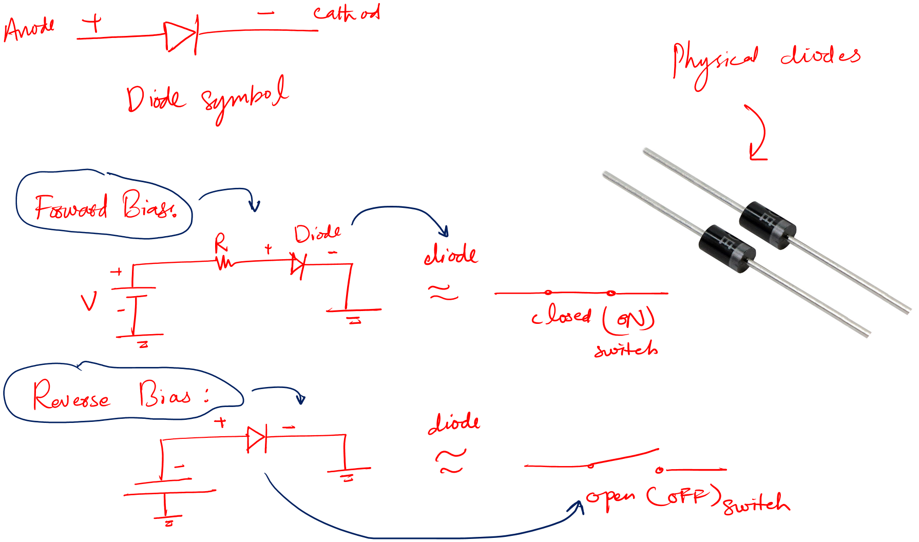
By forward bias I mean when the anode is connected to the positive terminal of the voltage source and the cathode is connected to the negative terminal.
Under this mentioned case (forward bias) diode becomes an ON switch with a voltage drop of only 0.7V (for the Silicon made diodes).
When the said condition is removed, the diode becomes like an OFF switch.
Now, this ON and OFF gives us a useful theory using which we can actually tell if the diode is good or bad.
How?
Let’s find out.
ON switch diode
A switch when in ON condition provides ideally zero resistance (R). But in reality, this resistance is very low.
We know that in the low resistance (LR) case there is zero voltage drop and any amount of current can flow through that resistance.
So, when a switch is ON, there should be zero voltage drop across it and maximum current should flow through it.
In the case of a diode, if we consider an ideal diode. The above is very true.
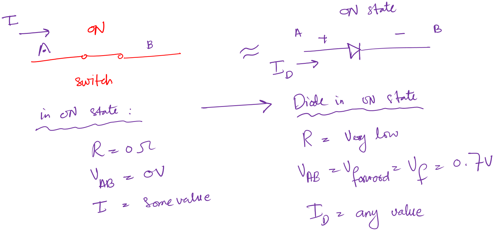
But in reality, an ON diode has a 0.7V drop across it. And maximum rated current can flow through it.
Now, to check if a diode is fine in the ON switch case:
There are two ways.
- Check for the low resistance (LR) in the ON state
- Check for the voltage drop in the forward bias case
The LR case: As you can probably tell. LR means low resistance. In this method, we measure the resistance of the diode using a multimeter.
And see if it is low enough in the forward case.
If it is low, we have a good diode.
But what if it is too low or too high?
Then we have two lousy diode cases:
- Short Diode
- Open Diode
Before jumping to these cases. Let’s first finish our second case, i.e., the voltage drop in the forward case.
Voltage drop: To tell a good diode. We measure the forward voltage drop across it. If this forward voltage drop (Vf) is 0.7V, then we can confidently say that the diode is good.
Else, the diode is no good and needs to be replaced.
OFF switch diode
Opposite the ON switch, there is an OFF switch condition. In this state, a switch offers ideally infinite resistance.
And no current can flow through it by whatever means.
Similarly, when we talk about diode in the OFF state. We are talking about it reverse bias case.
In reverse bias, the anode is connected to the negative terminal of the power source, and the cathode is connected to the positive terminal of the given voltage source.
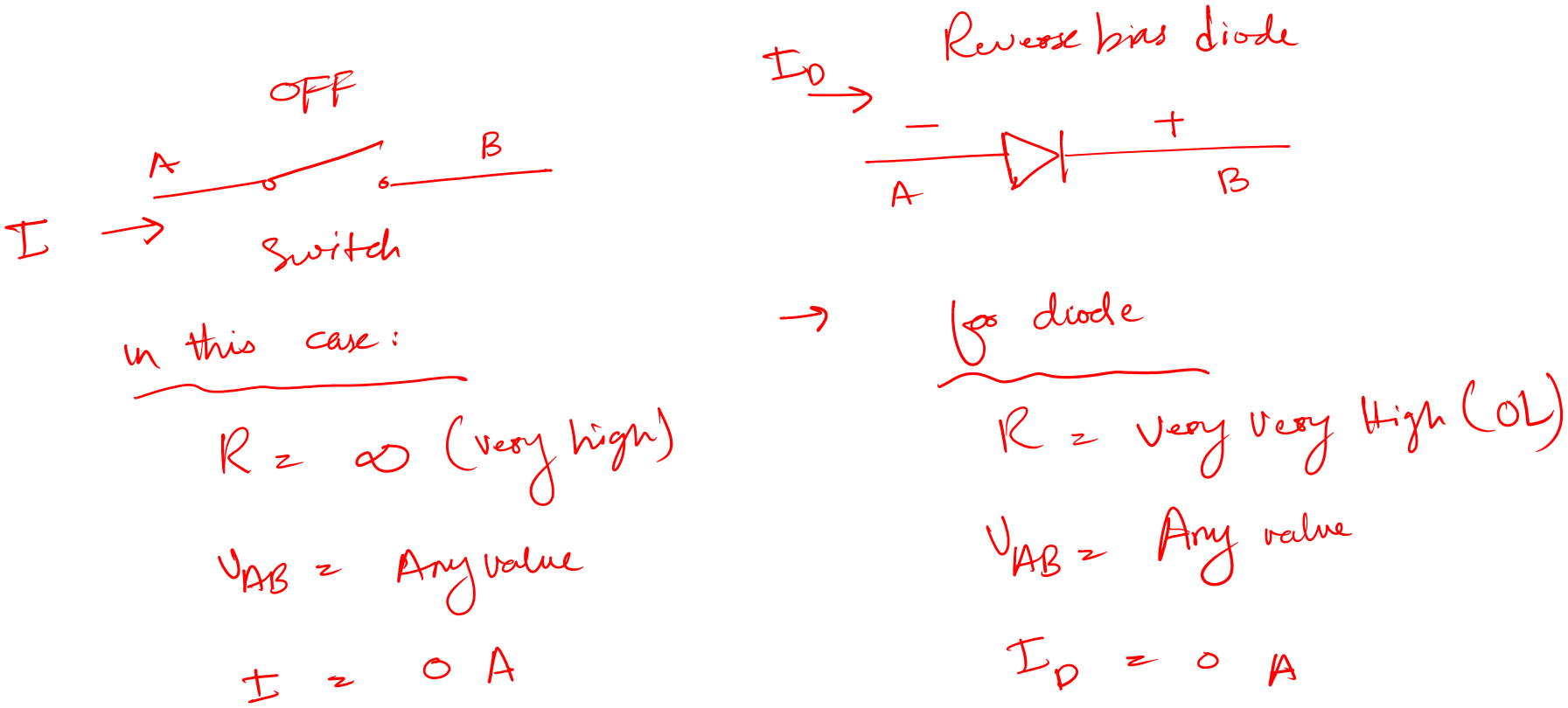
In this case, the diode is OFF and no current is supposed to flow through it.
Now to check if the diode is fine as an OFF switch as well:
There are the following two ways.
- Check for high resistance (HR).
- Check for the reverse voltage
In case of high resistance (HR): We connect the multimeter in resistance mode across the diode in a reverse mode and check the resistance.
If this resistance is high, we have a good diode.
Else we have a bad diode.
But if this value is too high or too low then we have the following lousy bad diode cases (just as we saw for the ON switch case)
- Short diode
- Open diode
Reverse Voltage drop: To tell a good diode. We measure the reverse voltage drop across it using the diode test function of a multimeter.
A good diode will give OL reading in the reverse bias case.
Else, the diode is no good and needs to be replaced.
Conclusion of ON/OFF switch diode
- In ON forward case: A good diode would give low resistance (using multimeter resistance function) and voltage drop of 0.7V (using diode test function)
- In OFF reverse case: A good diode would give high resistance and OL reading for voltage on the multimeter (using the diode test function).
A diode must pass both of the above cases. If it fails one of these tests, your diode is bad and needs to be replaced if it is in the circuit. Or should not be used if it is solo off the circuit diode.
Let’s talk about the unfortunate cases of a diode.
Open diode
An open diode is a diode that offers infinite resistance in both forward and reverse bias cases. Also, the voltage value is undefined for this case of a diode as well.
You can spot this diode on a circuit board immediately, it is busted open.
How to test this diode?
Well, the answer is simple.
We can go for either the resistance method or the voltage drop method.
For the resistance method: A multimeter will give you an undefined (OL) resistance value for most of the cases.
For forward and reverse both cases you should expect to see OL value on the multimeter screen. If the value is not OL then it would be some high random value. Indicating that the diode is open. And you should not use it in your circuit projects.
For the Voltage drop method: You should have OL value for forward and reverse cases using the diode test function on your multimeter.
Short diode
A short diode is a type of bad diode that offers very low resistance in both forward and reverse bias.
It is not necessary that you get a low value in both forward and reverse cases. If you get a low value in one of the cases, the diode is a bad one.
Now how do we test such diodes?
The answer is to look for resistance values. If the value is low in the reverse or forward case or in both. You have a bad diode, more specifically a shorted one.
Also, there is zero voltage drop across a shorted diode if you go for the voltage drop method.
Remember to properly go for the voltage drop method, always use the diode function on your multimeter. Don’t use the voltage function.
Diode testing methods
Let’s see how we can test the diode in or off the circuit board.
1. Visual inspection
As the name tells the whole picture. In this method, we try to figure out a bad diode just by seeing it. This method is so easy and effective because a bad diode is just shouting out loud in the entire circuit board.
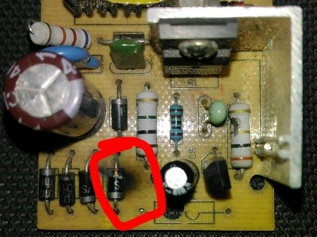
Usually following are the bad diode symptoms:
- You can clearly see it burnt out.
- It is broken
- There is a small crack
- The color of the body has been changed
- Terminals at the PCB board are turned black – in some cases
- Heats up way too quickly
- There is a noise in the system – if your diode is in the circuit, especially the ripples are increased in power supply output.
By applying the above you can eliminate the very obvious bad diodes. But you will find such cases in rare situations where there occurred a huge current flow.
Usually, circuits are protected from overcurrent flow. But this happens when the manufacturers want to save some costs while keeping the prices low for consumers.
2. Using a multimeter
For this method, we need a decent digital multimeter with a diode function. I will suggest Kelin Multimeter.
The key to this method is to find out if the diode is open or short. Because as we know, a diode can be completely short or open.
Open circuit test
Follow the following easy steps to identify a bad open diode:
- Take your multimeter and set it to the diode test function
- Take your diode
- Forward bias case: Connect the red probe (+ive) to the anode of the diode. And connect the black probe (-ive) to the cathode of the diode.
- Take the readings.
- Reverse the probe connection, i.e. make the diode reverse bias.
- Again take the readings
A good diode will show you reading between 0.4 to 0.8V in the forward case and will show OL in the reverse bias case
However, a bad diode will show OL in both cases. This means your diode is an open circuit.
Remember in diode test mode the results showing on the display are in mV range.
If you have Germanium (Ge) made diode then the reading for a good one will be between 0.2 to 0.5 V in the forward and will show OL in the reverse case.
Similarly, a bad Ge diode will show OL in both forward and reverse modes.
Short circuit test
The second bad diode symptom is that – a bad diode acts shortly in both forward and reverse bias mode.
Follow the same steps as we did for the open circuit test. Now, when you have the readings compare them to the following criteria.
As I shared above, a good diode will show a reading between 0.4 to 0.8V in the forward case and will show OL in the reverse bias case.
However, if you get the same results, i.e. approximately 0.4V in both cases. This means your diode is a short circuit. And it needs to be replaced.
No matter if your diode is open or short – both are bad diode symptoms and this diode needs an immediate replacement.
3. Using component tester
The above multimeter method requires careful readings. And it is subjected to human errors. Also, you need to have an understanding of how to use a multimeter.
I am not saying the above methods are bad or something. I am just saying we have an easy alternative to the above.
This method requires a new tool called the component tester. This component tester is an amazing and fun tool to have in our labs. It makes our lives easy and most importantly, it shows we have a deep love for electronic devices.
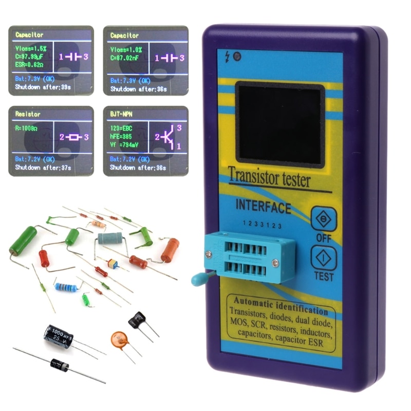
Following are the steps to use this tool for diode testing:
- Turn on the tester
- Place the diode you want to test
- Press test button
- See the results on the screen.
- If the diode is fine you will see a forward voltage drop of 0.7V for Si and 0.3V for Ge.
- If the diode is bad you will see no results (or a message on the display saying, bad component)– it is that easy.
As this method seems interesting. And you should try this definitely. But this method has a fundamental limitation. You can’t use it for in-circuit testing (the diode must be off the circuit).
Now, if the component tester mentioned above has got you curious and want to know more about it. Here is the link, M328 Component Tester (Amazon link), for your own further research and investigation.
Conclusion
You know a diode is one of the fundamental circuit components. You will find it in almost every electronic circuit.
But when it comes to identifying a bad diode we need to have an understanding of some bad diode symptoms. So that we can carefully replace the faulty diode from our circuit board.
A good diode acts short in forward bias mode allowing the current flow. And it acts open when reversed biased stops the current flow.
But the big symptoms of a bad diode are – it acts open both forward and reverse bias mode, or it acts short for both the mentioned modes.
In this article, we look at the different ways we can identify such a bad diode solo or in a circuit board.
Following are the methods we try to understand for easy diode testing.
- Method 1: Visual Inspection
- Method 2: Using multimeter
- Method 3: Using component tester
That is all I have for you to share. I hope you enjoyed my efforts.
Thank you…
Other useful posts: