

Regulated Power Supply Design [Guide 2026]
Hi. Hope you are having a good time. In this post, I share my learning about the regulated power supply.
Regulated is a general term used to define any type of power supply which has a stable output voltage or current independent of input or load. It may be a linear power supply, adjustable power supply or a variable power supply.
The only condition is, it must have output voltage or current independent of input (voltage) or output load (resistance or current).
If you were searching for just to know what is regulated power supply, I already gave you the answer. But if you want to study it completely, then you can follow my learning with me.
It will be fun.
Why a Regulated Power Supply?
Mostly, power supplies are designed for a dedicated load and environment. But sometimes main supply voltage, load, and surrounding temperature keep changing, altering the component parameters and hence changing the output voltage. Output voltage changes are undesirable.
Let me explain why output voltage changes are undesirable. Devices have minimum and maximum input voltage and current thresholds. And you have to follow these thresholds otherwise you may harm the device.
If your power supply output voltage changes, chances are it may cross these thresholds. This is why we need a constant output voltage. And this is achieved through a regulated power supply.
A regulated power supply can be any power supply, as I said the quality it should possess is a constant output voltage. A linear power supply, or an adjustable power supply, or a variable power supply can be a regulated power supply. It may have any voltage value, like 5V, 10V, 12V and many more.
An important point to keep in mind is, a regulated power supply is not always designed for just constant output voltage, it may be designed for constant output current.
With this, you might get the idea of what is the actual difference between the regulated and unregulated power supplies. Let me re-praise it down for your side notes:
The unregulated power supply has no output voltage or output’s current independent of its input main voltage or load.
General Design of a Regulated Power Supply
If you ask me to design a regulated power supply. I will immediately ask you, is it a regulated linear power supply with a fixed voltage, or adjustable power supply or a variable power supply?
Studying, in general, would a perfect solution for it, as the basic working principle of all regulated power supplies is the same.
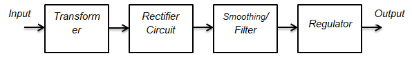
General Block Diagram
The design of any circuit begins with a well made general block diagram. It helps us to design the sections of the circuit individually and then at the end put them together to have a complete circuit, ready for use.
The general block diagram for this project is given below. It is very simple. You need to understand which block is doing what.
We will design each section first, and then put together each of them to have our DC power supply ready to power up our projects.
The Input Transformer
A transformer is a device which can step up or step down voltage levels, following the law of conversation of energy. Depending on your country, AC coming to your home has the voltage level of 220/120 V.
We need the input transformer to step down the incoming AC to our required level.
Be careful when playing with this device. As you are using the main supply voltage which can be too dangerous. Never touch any of the terminals with bare hands or with bad instruments.
Have a good and decent non-contact voltage tester and use it to always be sure of which line are live wires coming to a transformer.
The Rectifier Circuit
If you are thinking the transformer just stepped down the voltage to a desired regulated DC voltage.
I am sorry, you are wrong like once I was.
The stepped down voltage is still AC. To convert it into DC, you need a good rectifier circuit.
A rectifier circuit converts AC into DC voltage. Basically, there are two types of the rectifier circuit; half wave and full wave.
However, the one which we are interested in is a full rectifier, as it is more power efficient than half rectifier.
The Smoothing Capacitor/Filter
Nothing is ideal in practical electronics. The rectifier circuit converts the incoming mains to DC but unluckily it can not make it a pure DC.
The rectified DC is not very clean and has ripples. It is the job of a filter to filters out these ripples, and to make the voltage compatible for regulation.
A rule of thumb is DC voltage must have less than 10 percent ripples to be regulated perfectly.
The best filter in our case is the capacitor. You may have heard, a capacitor is charge storing device.
But actually, it can be best used as a filter. It is the most inexpensive filter for our basic 5V power supply design.
The Regulator
A regulator is the linear integrated circuit use to provide a regulated constant output voltage.
Voltage regulation is very important because we do not need a change in output voltage when the load changes. A load independent of the output voltage is always required.
The Regulator IC not just makes the output voltage independent of varying loads, but also from line voltage changes.
I hope you have developed some basic concept of regulated power supply design.
let’s go further with the actual circuit diagram for our specific 5V regulated power supply, so you may a very clear idea of designing.
The software which I will use is NI Multisim, hope you are familiar with it. If you are not familiar with it, no problem. It is not necessary. You can use any software. The main purpose is to learn the design, not simulation software.
Regulated Power Supply Design (with fixed voltage)
The following design steps cover the design of a regulated power supply with fixed output voltage or adjustable/variable power supply. With these steps, you can design your regulated power supply.
I am going with a specific example of 5V because I think it would be best, in this way, to understand the whole design process.
Now, you are thinking, I would start an explanation from the transformer but it is not the case. A transformer is not selected at the very first.
Below is the circuit diagram for the said project. You get the main supply, voltage and frequency can depend on your country; fuse, to protect the circuit; transformer, rectifier, capacitor filter, an LED indicator, and the regulator IC.
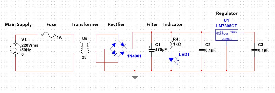
The block diagram is implemented in NI Multisim, a good simulation software for students and electronics beginners. I encourage spent some time playing with it. As, in my opinion, you should have a strong knowledge of simulation software in order to do fun things in learning basic electronics.
Step By Step Method to Design 5V DC Power Supply
You are thinking, I would start the design explanation from the transformer but it is not the case. A transformer is not selected at the very first.
Step 1: The Selection of Regulator IC
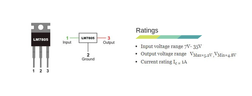
The selection of a regulator IC depends on your output voltage. In our case, we are designing for the 5V output voltage, we will select the LM7805 linear regulator IC.
Next thing is, we need to know voltage, current and power ratings of selected regulator IC.
This is done by using the datasheet of regulator IC. Following are the ratings, pin diagram for LM7805.
Datasheet of 7805 also prescribes to use a 0.1μF capacitor at the output side to avoid transient changes in the voltages due to changes in load.
And a 0.1μF at the input side of the regulator to avoid ripples if the filtering is far away from the regulator.
Step 2: The Selection of Transformer
The right transformer selection means saving a lot of money. We got to know, the minimum input to our selected regulator IC is 7V. So, we need a transformer to step down the main AC to at least this value.
But, between the regulator and transformer, there is a diode bridge rectifier too. The rectifier has its own voltage drop across it, i.e. 1.4V. We need to compensate for this value as well.
Mathematically:
%0A)
This means we should select the transformer with a secondary voltage value equal to 9V or at least 10% more than 9V.
From these points, for 5V DC power supply design, we can select a transformer of current rating 1A and secondary voltage of 9V or 12V.
Step 3: The Selection of Diodes for Bridge
You see, the rectifier is made by arranging diodes in some pattern. To make rectifier we need to select proper diodes for it. When selecting a diode for the bridge circuit.
Keep in mind the output load current, and maximum peak secondary voltage of the transformer i-e 9V in our case. Instead of individual diodes, you can also use one individual bridge that comes in the IC package.
But I don’t want you to use here, just for purpose of learning and playing with individual diodes.
The selected diode must have the current rating more than the load current. And peak reverse voltage (PIV) more than peak secondary transformer voltage.
We select IN4001 diode because it has the current rating of 1A more than our desire rating, and peak reverse voltage of 50V.
Step 4: The Selection of Smoothing capacitor and Calculations
Things we need to keep in mind while selecting a proper capacitor filter are, its voltage, power rating, and capacitance value. T
he voltage rating is calculated from the secondary voltage of a transformer. Rule of thumb is, the capacitor voltage rating must be at least 20% more than the secondary voltage.
So, if the secondary voltage is 17 V (Peak value), then your capacitor voltage rating must be at least 50V.
Second, we need to calculate the proper capacitance value. It depends upon the output voltage and the output current. To find the proper value of capacitance, use the formula below:

Where,
Io = Load current i-e 500mA in our design, Vo = Output voltage i-e in our case 5V, f = Frequency
In our case:
Frequency is 50Hz because in our country mains AC is 220 @ 50Hz. You might have 120V @ 60Hz mains AC. If so then put the values accordingly. Then by using capacitor formula, the practical standard close to this value i-e 3.1847E-4 is 470uF.
Another important formula from the book “Electronic Devices by Thomas L. Floyd” is listed below. This can also be used to calculate the capacitor value.
In this case, R is load resistance. And Rf is ripple factor, which should be less than 10% for a good design. And with this, we just finish designing 5V power supply.
Make The Power Supply Safe
Every design must have a safety feature to protect it from burning. Similarly, our simple supply must have a one i.e. the input fuse. The input fuse will protect our supply in case of overloading. For example, our desire load can handle 500mA.
If in case our load start to miss behave, there is a chance of burring of components. The fuse will protect our supply. A rule of thumb for selecting the fuse rating is, it must be at least 20% more than the load current.
The simple power supply we designed has the capability to deliver 1A current, which in some case you can use it for. If you decide to use it for such cases, then don’t forget to attach a heat sink to the regulator IC.
5V Power Supply Kit (DIY)
So, we got some basic knowledge of how a simple 5V power supply is designed.
For me, if you are an electronics hobbyist or beginner, learning some basic electronics, I would recommend you to design your own lab power supply. It would be a very good decision.
It will help you learn electronics as well as give you the best lab power supply.
I call it the best one because you will make it yourself. And I cannot put it in words how much fun it is to play with electronics in a safe environment. It is like learning from doing.
I recommend Elenco power supply kit (Amazon Link) to start with. It is affordable, high quality, and well documented to guide you with each step. Trust me you will learn a lot. You will learn how to solder, assemble, and make an end product like you always see in different stores.
Regulated Power Supply Design (with adjustable/variable output)
Most of the time we do not need a fixed voltage. Sometimes we need a variable power source.
For example, to check the transistor collector currents for different base voltages, we a need a variable power source. And this variable voltage must be regulated.
The design procedure is the same as I explained above with little changes at the output regulators.
This time we would require a variable resistor so that by varying its resistance we will have different voltages. Following is the schematic for adjustable power supply or variable power supply:
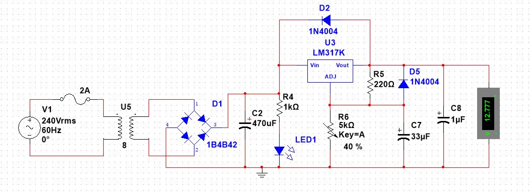
Up to led portion, the circuit is same as was for regulated power supply for 5V @ 500mA. The circuit becomes complicated after the led portion, isn’t? Do not be afraid. It is very simple. A variable resistor is for to vary output voltage.
Diodes are used for protecting the circuit from the back current. Now, let’s see in the following video how varying the resistor changes the output voltage.
Advantages of Regulated Power Supply
A supply with regulated output has many advantages. Following are of the key importance.
- low noise levels
- low-cost
- simplicity
- reliability
Regulated power supply are very simple to design, you might have felt it in this post. Simple design makes it very cost effective. These power supplies have low cost and are very reliable.
They are relatively noise-free. Linear regulators ICs which are used at the output, have a low output voltage ripple making them best suitable for applications where noise-sensitivity is essential.
Conclusion
The design power supply would be fine to power up your other small projects or brings you good grades/money if you are assigned to a similar project. I do not know why, but I feel confident if you follow the same easy steps with me you will have your first designed power supply.
Please do not specify it to just 500mA supply. It can be your 5V DC power supply in general with up to 500mA current capability.
Just for extra knowledge, for positive voltage output use LM78XX. XX indicates the value of output voltage and 78 indicates positive output. For negative voltage output use LM79XX, 79 indicate negative voltage and XX indicates the value of output.
With above said, design of a regulated power supply came to its end. Hopefully, you have enjoyed it.
Thank you and have a good life.
Other useful posts:
Where did you get the Spice code or database for the LM7805 and LM317 to be simulated? I have Multisim 14.0 and am trying to make a similar regulated power supply. Thanks
Paul download this design file, open it in Multisim. Then right click on each component and save it in you database. Now, you have LM7805, 317 in your database you can use them in your project.