

Design a resistor voltage divider [Step by step 2026]
A resistor voltage divider is useful when we have a single power source, and we want to divide it further into our desired reference values.
For example, if we have a source of 10V, but our reference requires a 5V, then a good voltage divider circuit will help us here.
At the end of this article, you should be able to:
- Design your own resistor voltage divider circuit for your projects
- Learn the theory behind the design
- Few practical tips
Sounds interesting? Then, let’s get started.
Resistor voltage divider design
A voltage divider is a very basic resistor circuit when it comes to circuit design.
It plays a key role when different levels of voltages are required within the same circuit. As the name suggests, a voltage divider is a circuit that divides the input voltage into the required reference levels.
Let’s have a look at a voltage divider circuit.
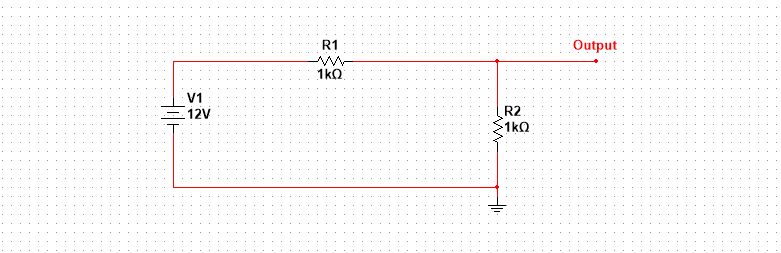
Look at this guy, it is maybe confusing. I know, but this is the simplest one in the entire circuit design.
And by the way, I used Multisim simulation software for this circuit.
The above circuit is just a simple form of a voltage divider. Let’s see how this guy can confuse us in different forms.
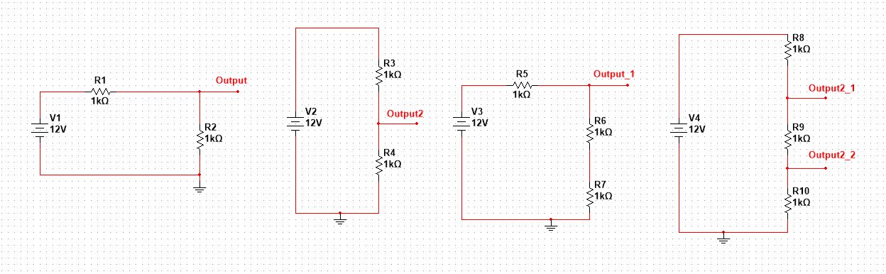
The output voltage can be between a node and reference ground, or it may be the difference between two nodes as well (see the last diagram).
No matter how many resistors are being used, remember if they are at the end making a series type connection, chances are it might be a voltage divider.
There are so many ways you can use it according to your application, but most generally it is used as a reference voltage.
In simple, it is best used to make a reference voltage level.
The accuracy of the output voltage is amazing if we play nice when selecting load, or resistor values.
Selecting load is something we mostly can’t control, but we are in control of designing the divider resistance values.
Alright!
Let’s jump into the actual design.
Voltage divider formula derivation
Almost every circuit design has its formulas. According to these formulas, we calculate the values of the components used in that circuit.
The voltage divider is no different.
It has a specific formula that helps us set the resistor values according to the required output voltage.
Let’s try to understand and derive that formula.
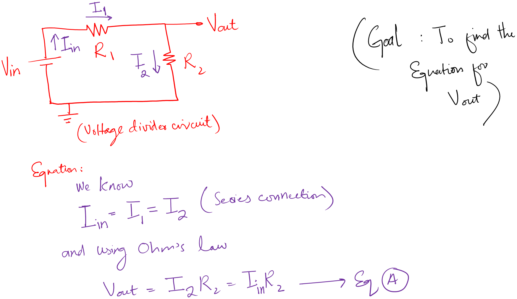
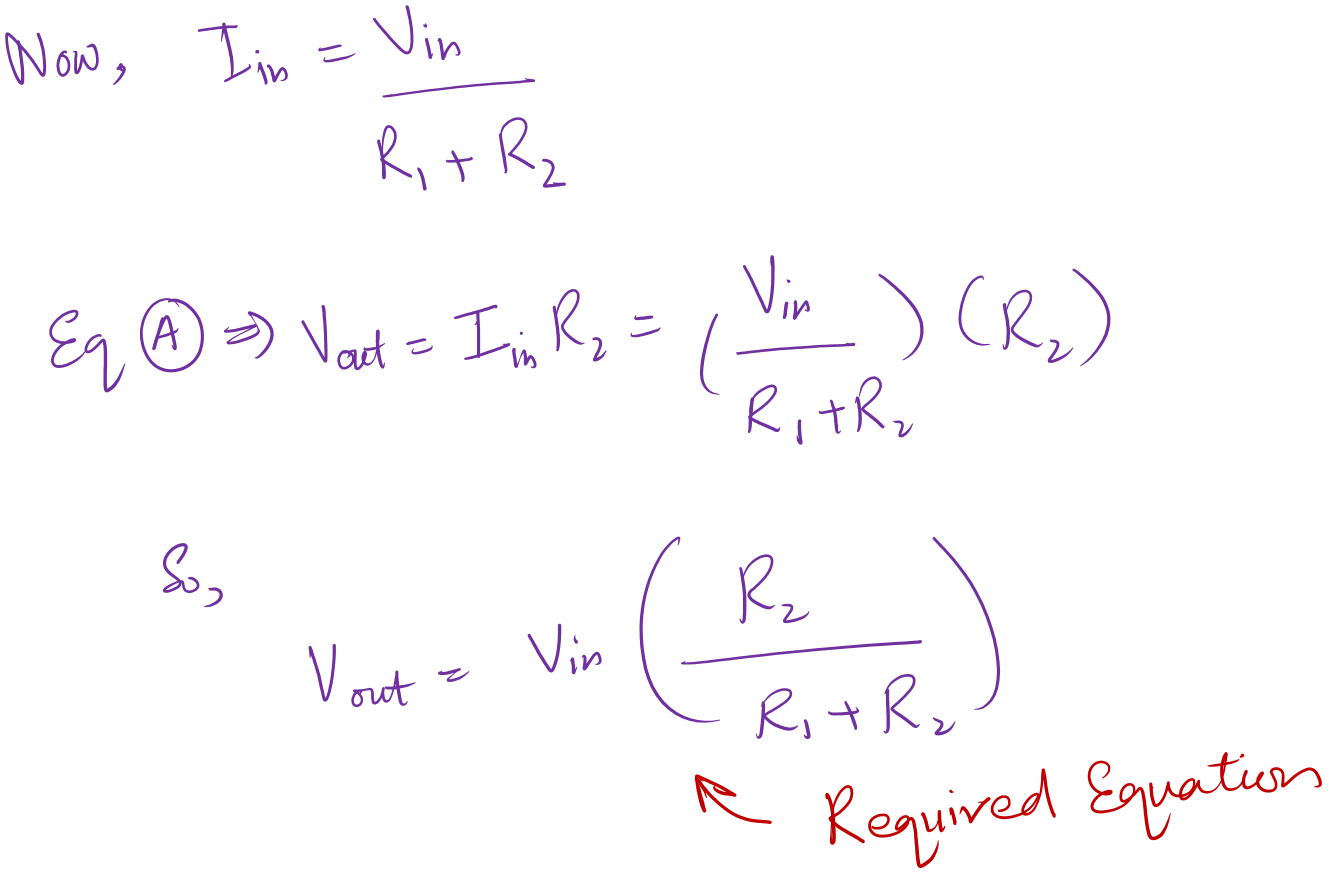
The above formula is the backbone of the design procedure. Try to derive it once yourselves and try to understand it.
Hopefully, you will have fun.
Alright!
Step by Step Design Process
Now, we will use the above derived equation and try to find out the values of resistors in the divider circuit.
Step 1: Define the output voltage
The first step in voltage divider design is to define the output voltage. Like, for which voltage level do you want to design the divider circuit?
Mostly, the divider circuit is used for voltage reference.
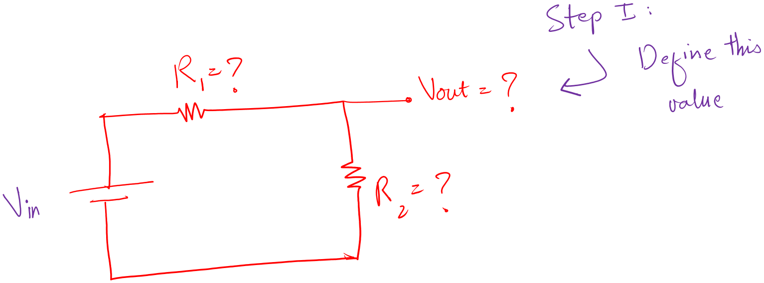
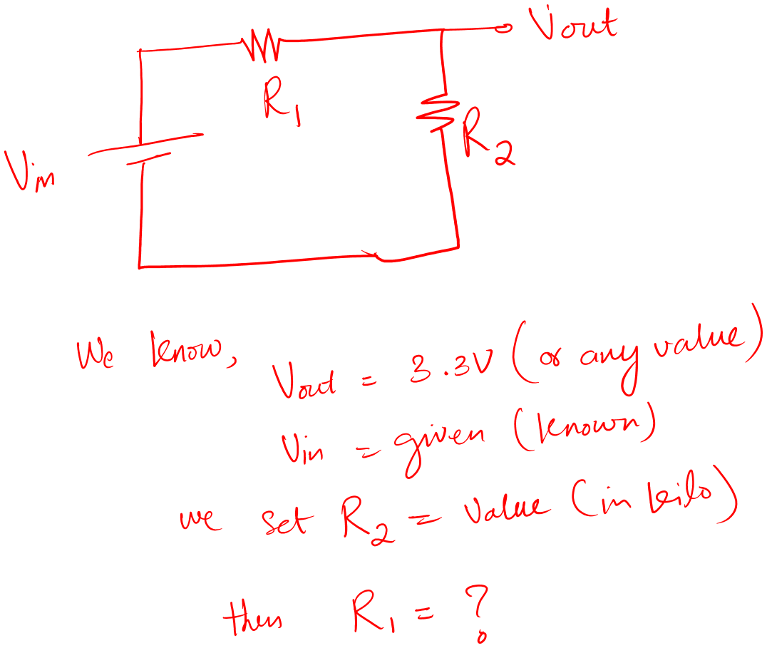
Let say we want a reference voltage of 3.3V for the application, then 3.3V is our required output for the divider circuit.
You can set Vout to any value.
Always keep in mind, a voltage divider should not be used for powering up devices. It is not meant for powering high power devices.
Sure you can use it for low power devices like LEDs.
The reason is, it’s not stable. High power devices need high current, which means high heat across R1. This may lead to burning the poor resistor.
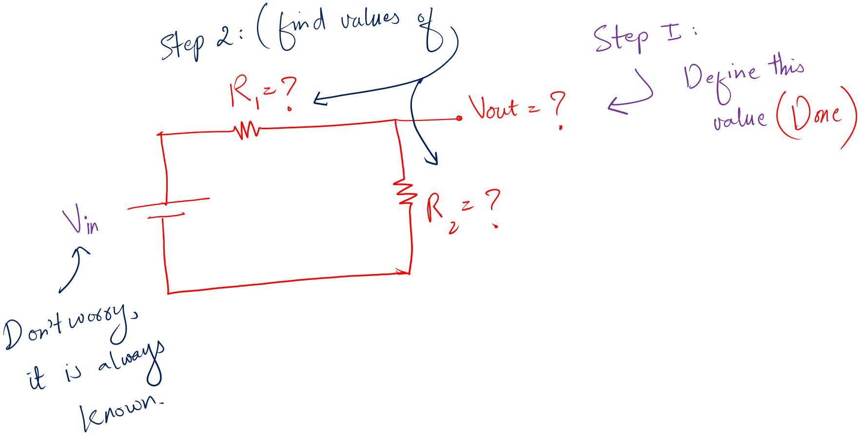
Step 2: Calculating the resistor values
This is a fun task. In theory, you can design any voltage divider circuit, but in reality, you are limited.
You can’t choose random resistor values, because these values must be available in the market to practically implement the circuit, i.e., they must be standard values.
For example, you select random values, go to the store and find out no such values exist.
Congrats, you just designed a very poor divider circuit.
Now, some of you would say, we can use series and parallel to get the value of our desire.
My answer is true, very true. But it will make your design ugly and full of resistors and a lot of energy wastage.
You can’t use the low resistor values. The reason is, we don’t want any power loss at the divider circuit. We want it just as a constant voltage reference.
The above two tips are very important. Keep them in your mind.
Now, to calculate the resistor values:
Select the value of R2 first then calculate for the value of R1.
Choose the values in Kilo. Don’t go for low resistor values, it will cause power loss in the circuit.
So, you select the value of R2 on your own. Now we know Vout, Vin, and R2, then by using equation (A) we can find the value of R1.
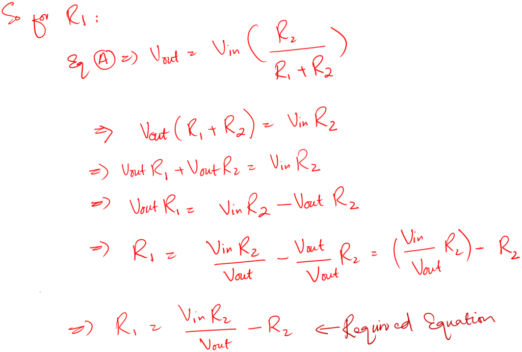
And that is how we design a resistor voltage divider circuit for any value of Vout.
Resistor voltage divider examples
I think it is time for some examples to make it clear.
Example without load
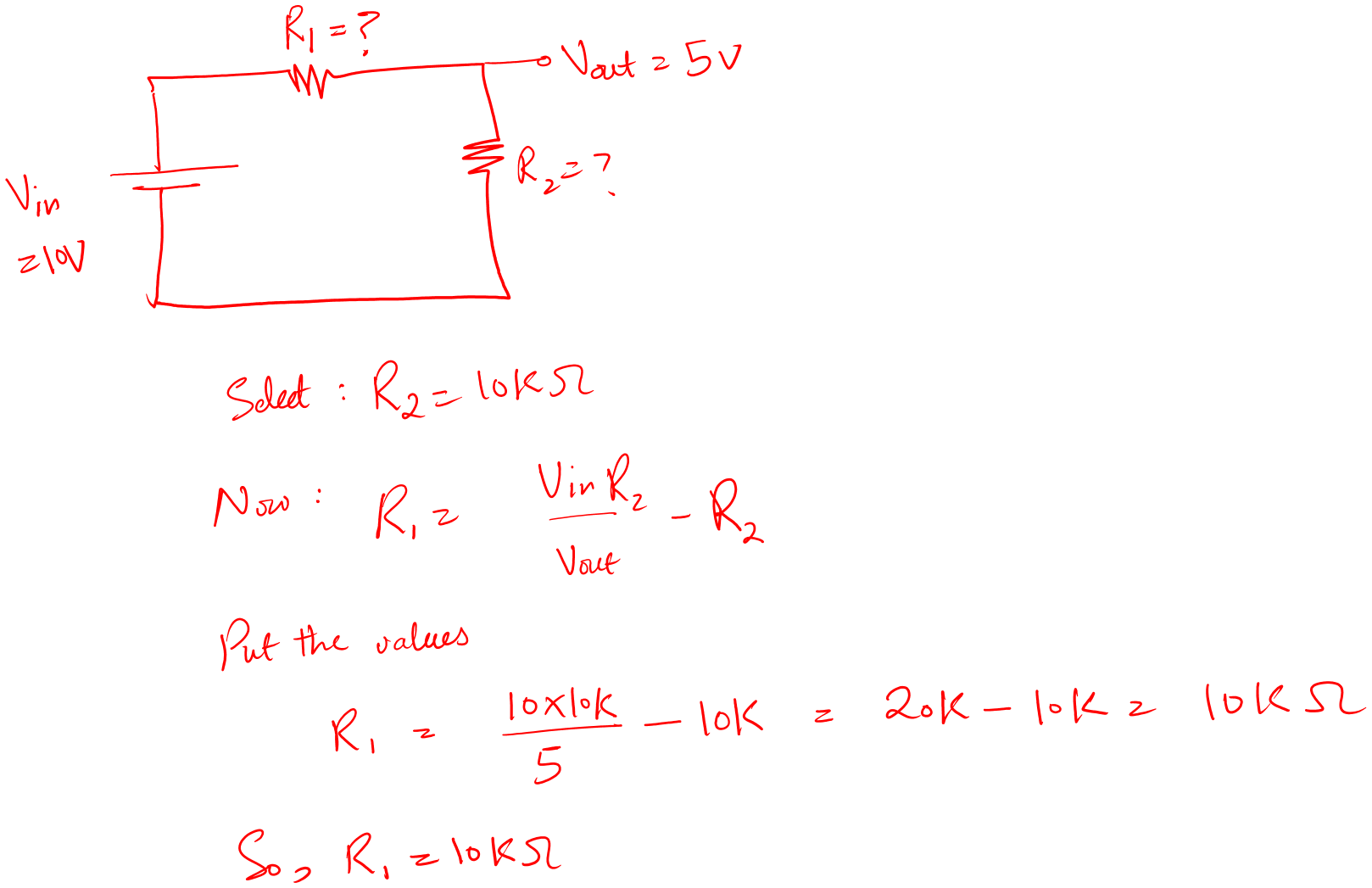
Design a voltage divider circuit for an output voltage of 5V. The input voltage is 10V.
Solution:
- First thing, note the input and output voltages, the output is half the input.
- Second, try to select standard values within the range of kilo Ohms. So, the best values for this case are 10kOhms.
- There are many other values possible, you can go with that as well.
Let’s verify this resistor value.
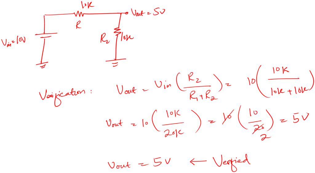
But remember we have not connected this to the load yet, and load is another factor to be considered when choosing values for resistors.
Example with load
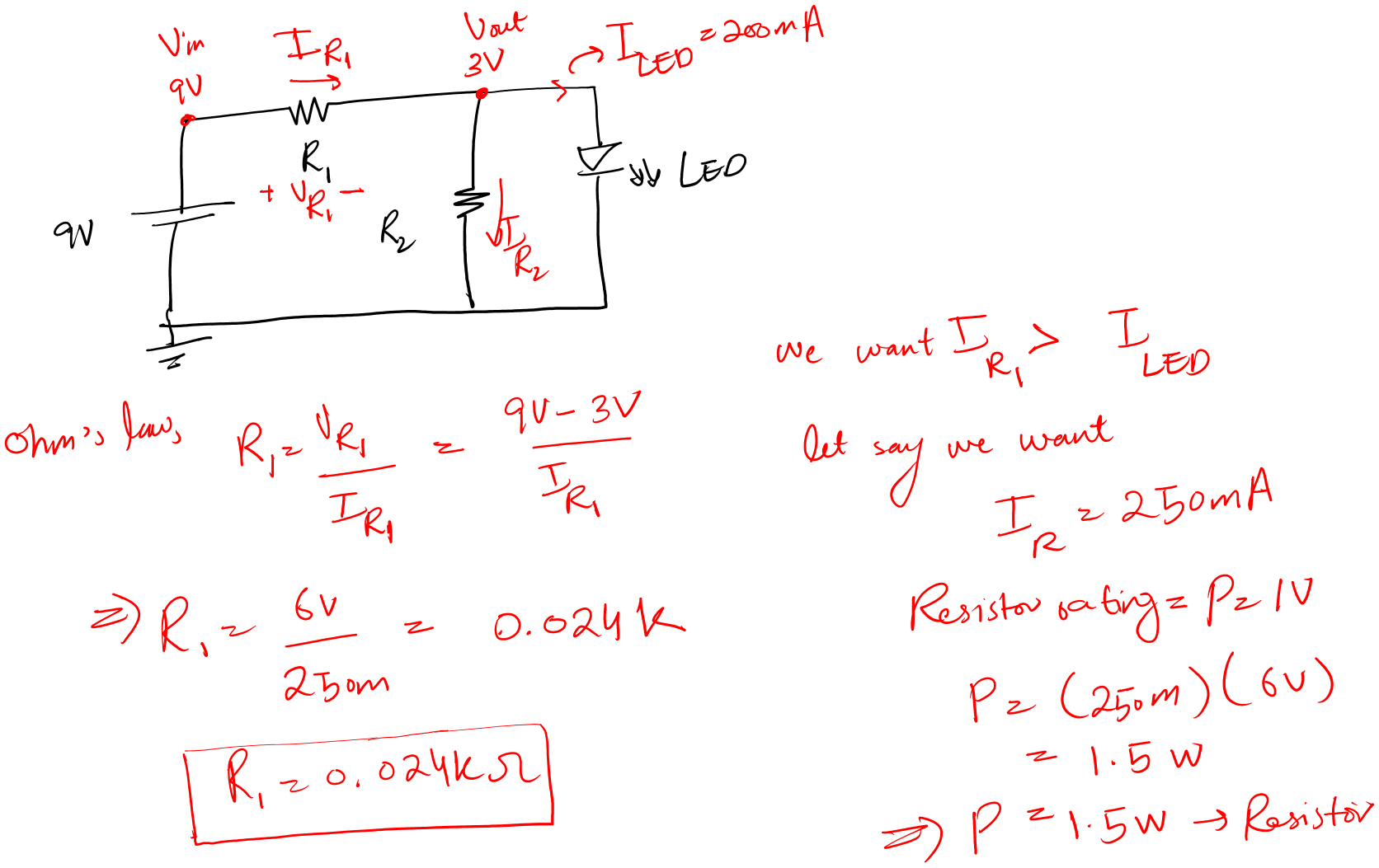
Design a voltage divider circuit for an LED load 3V @ 200mA. The input voltage is 9V.
Solution:
- First, we have an LED with ratings of 3V @ 200mA.
- This means that Vout is 3V
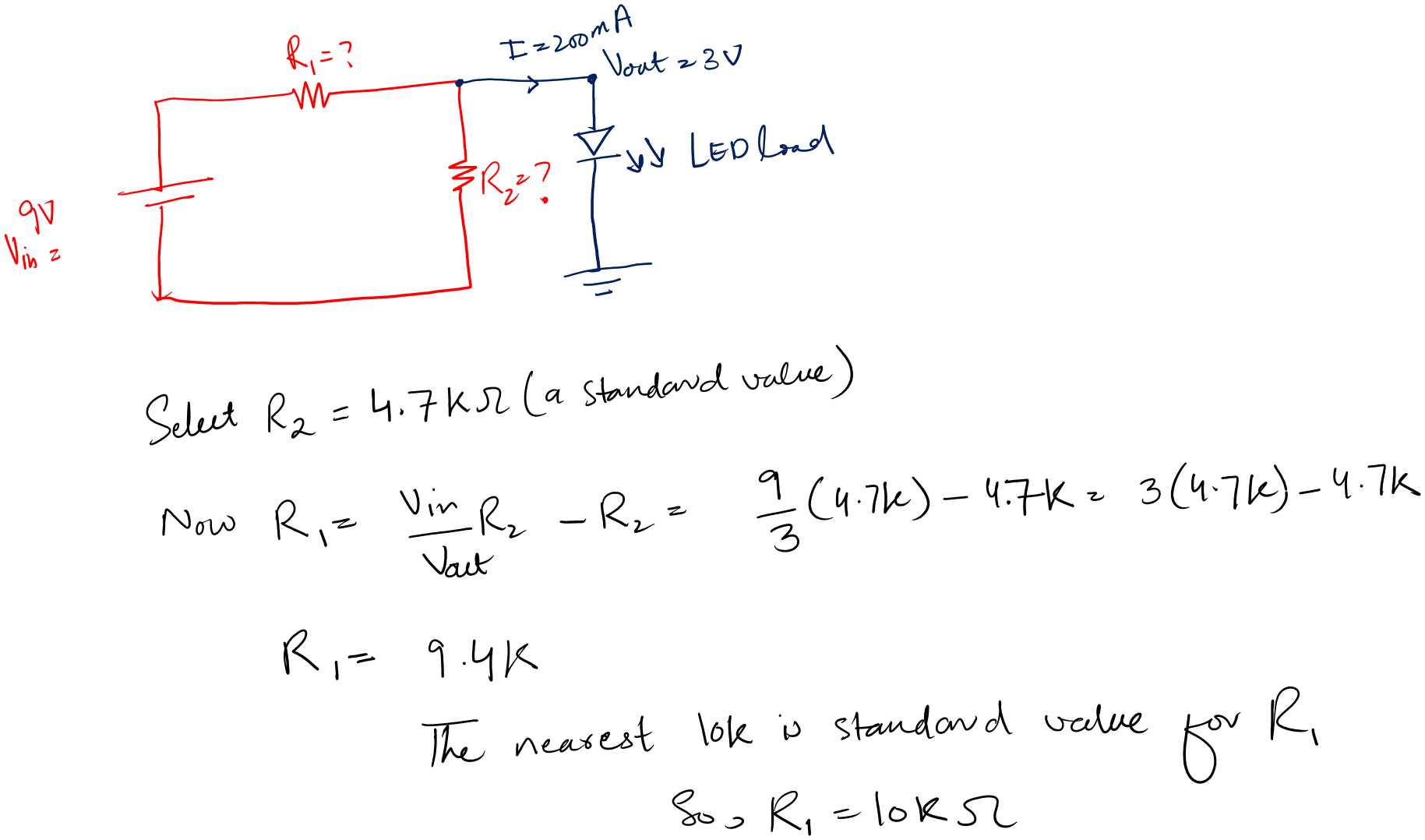
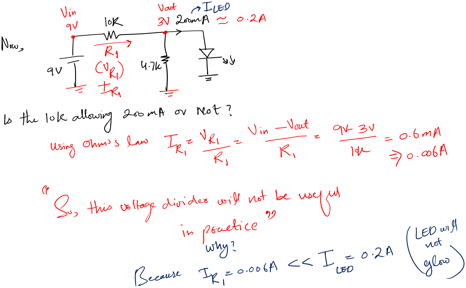
You see, the above design is good on paper. But this is not the useful one.
So how to correct this design?
We first calculate the value of R1 to ensure it allows the amount of current we require for the LED to glow.
After that, we will rearrange the voltage divider equation for R2. And calculate the R2 value.
Let’s see the math.
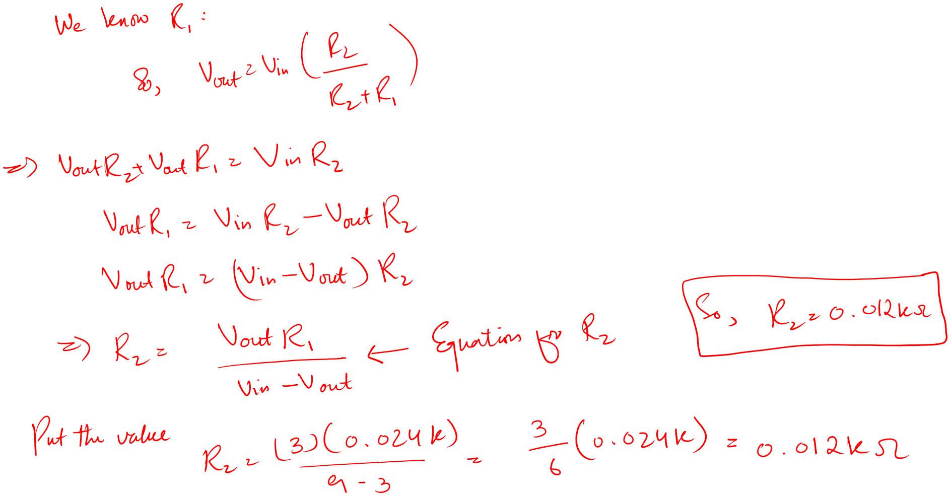
Now, you can see yourself. A voltage divider is not a source provider when you require high power.
It is best for voltage reference purposes only.
Resistor testing for divider design
Let’s say, you want to implement a voltage divider on a breadboard.
First, you design a voltage divider, i.e., calculate all the values.
Second, you need to measure these resistor values practically before putting them into the breadboard.
To measure resistor value you use a multimeter. How?
- Turn on your multimeter
- Select the resistance functions
- Connect the probes of the multimeter to the terminal of the resistor.
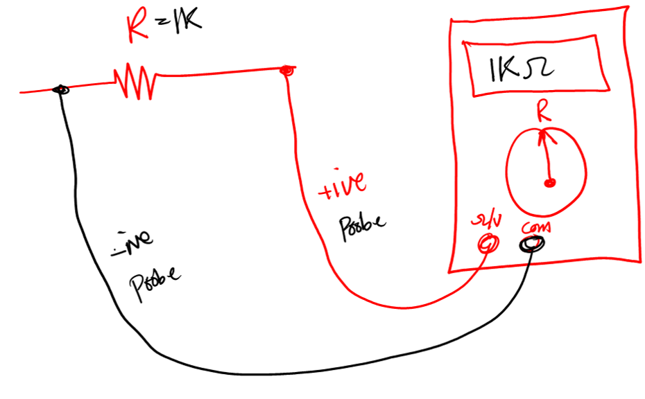
- Get the results on the screen
Besides this method, there is a new way of testing resistors as well.
And that is by using a component tester, like the m328 tester (product link).
- Take m328 tester and turn it on
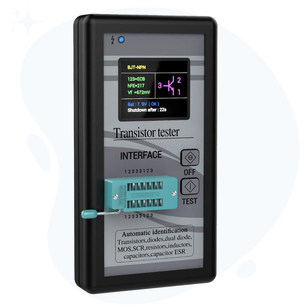
- Put your resistor in the tester
- Press the test button, and get the results – it is that simple.
- The meter will give you its resistance value. Also, tell you if the resistor is good or bad.
M328 tester can be of great help when there are a lot of components to be tested for your projects.
Conclusion
Sometimes we require various reference voltage values in the same circuit.
Since circuits have one voltage input source. We use the resistor voltage divider technique to divide that one source into our required values.
Why? We don’t put many voltage sources instead of a voltage divider circuit. Simply, it is not practical.
So, that is it. That is all I want to share about voltage divider circuit design. I hope I was helpful.
I believe if you practice what I shared above, you will be able to design a working divider circuit for your own projects.
Now, it is your turn. Share in the comments section below which part of the article you enjoyed. If you have any confusion let me know as well.
Share this article with your friends. It helps me a lot.
Thank you and have a grateful life.
**We learned how to design a voltage divider. To continue your learning you can explore how to test a resistor before we use it our projects.
Yaman: I am trying to design a small circuit to power about 6 small SMD0603 white 3v LED lights off of a 5v DC input for a minature diorama I am making. (Or I could use a 9v supply if needed) I understand they run about 20ma max. All these companies selling the lights suggest running resistors in series with each LED, but couldn’t they all be run in parallel off a voltage divider circuit? If I have a 5v in and R1= 2k and R2 = 3k Vout should equal 3v So if I hook my 5 LED lights up to this in parallel is that a better solution than having a resistor on each LED light in parallel off the 5v supply? Thanks
Hi. Remember voltage divider are used for “reference voltage levels”. It is not best for powering up other devices.
Taking your mentioned case: Placing all leds in parallel seems a nice solution in theory but in practice R1 is limiting the current flow which will be divided amoung all the leds making them to glow dimmer. Voltage may be the same across each led but small current will be flowing. To make them glow brighter you need to lower the resistor value which inturns need you to increase its power ratings. Now you got the point that it is hard to use voltage divider as realiable power source.
I hope I answered your question Doane.
I need help in tuning the circuit
Can you do that for frequcy and resinance
Hi. I would love to help you to the best of knowledge. Please feel free to share the details here (Personal contact form).
Have you seen the don smith generator