

Pin configuration of any component is important. Because if you wrongly place a component in the circuit.
There is a chance the circuit will not work. In the worst case, you may end up burning your component as well.
Similarly, finding the potentiometer pins configuration is essential. But beginner people find it hard to do so.
But not anymore…
At the end of this article, you should be able to:
- Find the correct potentiometer or variable resistor pins configuration
- You will know which terminals are fixed and which one is the variable one
Sounds interesting? Well, then let’s get started.
Potentiometer pins configuration
A potentiometer also known as a variable resistor is a three terminal component that has the capability of adjustable resistance.
We can change the resistance of a potentiometer according to our requirements.
Following is the circuit symbol and a few physical potentiometers:
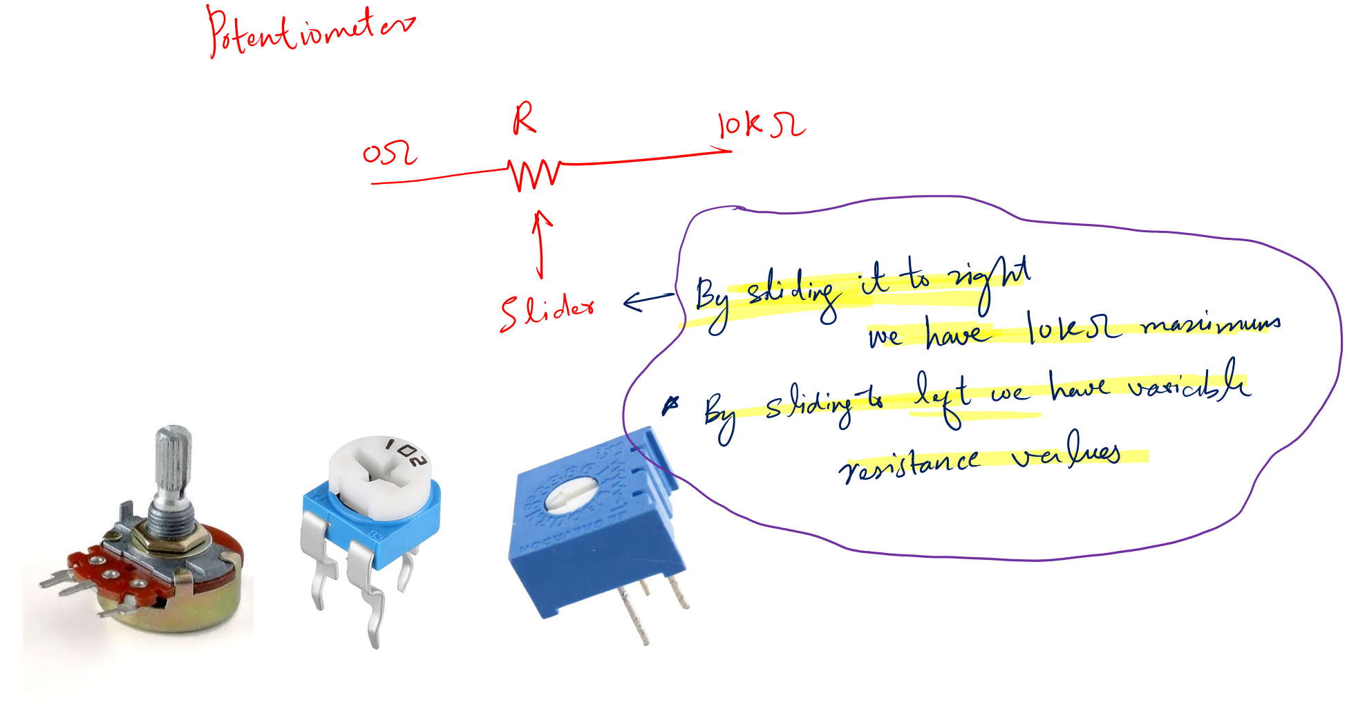
The terminal marked as 0 and 10k are the fixed terminals. Meaning that the resistance value between them is fixed, i.e., 10KOhm.
The third terminal is the slider. We can move this slider left or right and can have the resistance value of our choice.
You see in the above picture some various physical potentiometers as well. They are of different shapes, and we work with them according to our circuit design requirements.
Despite the shapes, we need to identify the right pins before we put them in our circuit.
To do so we can use two methods:
They are as follows:
- Identify the potentiometer pins using a multimeter
- Identify the potentiometer pins using a component tester
Let’s explore these in detail.
1. Using a multimeter
A multimeter is a basic electronic measuring instrument that helps us measure:
- Resistances
- Voltages
- Current
- Capacitance
For finding the right potentiometer pins configuration we require to have a decent digital multimeter like this one (Amazon link).
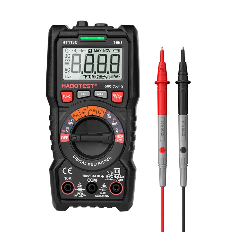
First, take your multimeter and the potentiometer you want to find the correct pins. Follow the following simple steps.
- Set the multimeter to resistance mode.
- As we have two multimeter probes and three terminals of the potentiometer. Connect the probes to any of the two (start from the left side)
- Change the slider
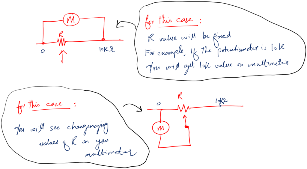
- If the value on the screen changes – this is your slider terminal. If not then the terminals are the fixed ones.
2. Using a component tester
While a multimeter just does the measurement and leaves the testing to the person’s knowledge and experience.
A component tester solves this problem. And tell you directly if the component is bad or good. Leaving the guesswork.
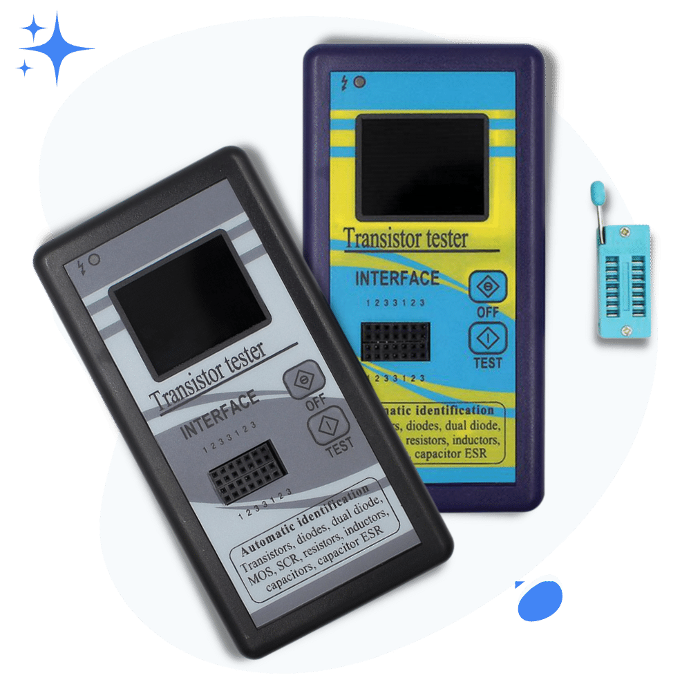
Well, for this method we need to have a component tester like the M328 tester (Amazon link).
Following is the picture of the component tester I have for testing various types of electronics and electrical components.
Follow the following simple steps to find out the pins of a potentiometer:
- Take your component tester and turn it on
- Take your potentiometer and connect it to the component tester
- By connecting I mean plugging the potentiometer into the socket of the tester
- After that, press the test button
- And see the exact pin configuration on the screen of the tester.
It is just that simple.
Other than this method, you can use a multimeter as well. But at the beginner level using the multimeter is subjected to many errors. This method is more safe and easy to implement.
Just for beginners which don’t know what a component tester is. Basically, a component tester is an electronics tool that helps us find the:
- Correct pin configuration of various components like transistors, capacitors, and so many more.
- Help us test the component.
- By testing, I mean to tell if the component is good or bad.
- A component tester also helps us measure various component related parameters as well.
- For example, with a transistor, we not only get the correct pin configuration but also the DC best value as well.
Alright! Let’s now see how to put a potentiometer in a circuit correctly.
Correct way of placing a potentiometer in a circuit
Now that we have correctly identified the correct pin configuration of a potentiometer. It is also the time to learn how to place in a circuit correctly as well.
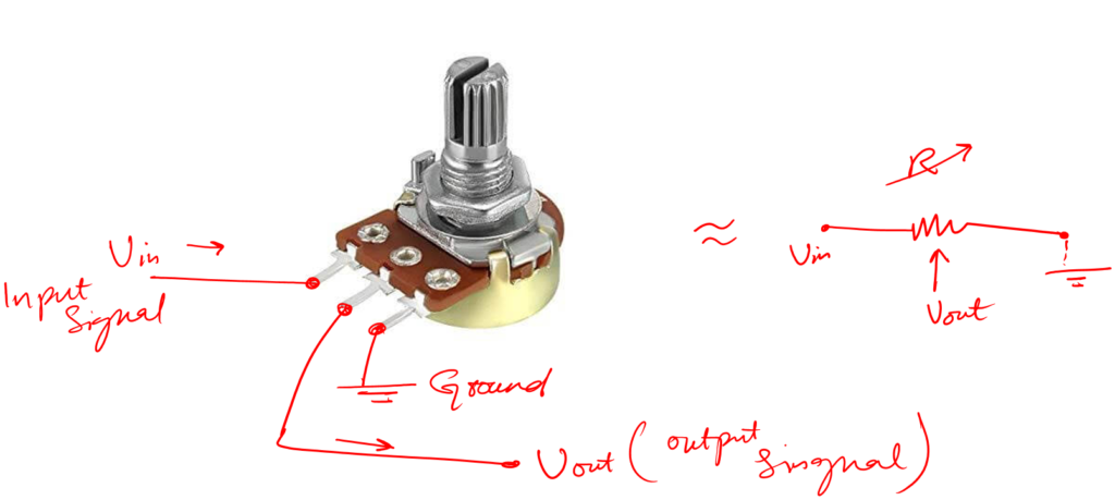
Your slider terminal should be connected to the output. While any of the fixed terminals can be ground or input.
Conclusion
A potentiometer also known as a variable resistor has three terminals. Two of them are fixed while one is a sliding one. The sliding one changes the resistance value as we move or rotate it.
The correct identification of these terminals is very important.
Because if we don’t connect the potentiometer pins the right way in our circuits. There is a high chance the circuit will not work properly.
You will see potentiometer in various shape and sizes. But they all serve one single function. To provide a variable or adjustable resistance.
So to find the right potentiometer pins configuration there are a few ways:
- The first method is to use an online data sheet of the given potentiometer. In the datasheet, you will find the exact pin configuration.
- The second method is to use a digital multimeter
- The third way is to use a component tester
Finding the right pin configuration means to tell which terminal is the fixed one and which one the slider terminal.
Usually the middle terminal is the slider one, but it is always recommended to first conform it before placing the potentiometer in the circuit.
Among the three given methods, multimeter method is effective. But if you want to save yourself sometime then go for the component tester method.
Because in component tester method. All you need to do is put your potentiometer in the tester and press test button.
The component tester will automatically tell you the right pin configuration of your given variable resistor or potentiometer.
So that is it. That is all I have for you about telling the right pins of a given potentiometer. I hope you enjoyed my limited knowledge efforts.
I meet you in the next electronics article. Take great care of yourself.
Thank you and have a grateful life.
Other useful posts: