

Variable resistor basics for beginners (Guide, 2026)
A resistor is a component that offers a fixed amount of resistance value. But there is also some resistor that offers variable resistance.
A variable resistor, or potentiometer, is a resistor whose resistance can be adjusted manually, allowing control over current flow in a circuit. It typically has three terminals: two for the fixed resistance and one connected to a movable wiper. By rotating or sliding the wiper, the resistance changes, making variable resistors useful in applications like volume control, dimming lights, and tuning circuits.
In this article, we’ll learn about variable resistors basics along with how to measure and test these types of resistors.
Variable resistor basics
You know, let’s say you have to design an amplifier. One of the parameters of your amplifier should be that it can decrease and increase the sound or music level.
In that case what you would do?
Well, we can use a variable resistor there to increase or decrease the gain levels of transistors. Thus making us able to lower or increase the music level.
Now how a variable resistor would achieve those results?
Simply because a variable resistor can change its resistance value. This change in resistance value changes the design calculations of a circuit. And thus we have different results from the same circuit.
Let’s talk about the proper definition of a variable resistor.
Definition of a potentiometer
A variable resistor is also called a potentiometer. So, the proper definition of a potentiometer would be like this:
A variable resistor or a potentiometer is a resistor which can change its resistance value, i.e., it has adjustable or variable resistance.
The reason it is also called a potentiometer is that with resistance variation, it changes the voltage or potential values. Thus changing the voltage level in the same circuit – gives us different results.
Circuit symbol and physical representation
Every electronic component has its circuit symbol. A circuit symbol helps us draw the circuit on paper for our analysis and design. Also, with the circuit symbol, we can simply design our circuit in simulation software.
Following is the circuit symbol of a variable resistor and some actual physical variable resistors.
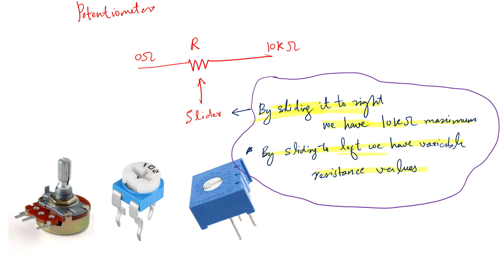
In the circuit symbol, you can see that it has three terminals.
Two terminals are fixed (0-10K) while one is the slider. With the help of this slider, we can change the resistance value.
In the above picture, you should also see various physical versions of a potentiometer. They come in various shapes and sizes, but they work on the same principle.
The slider in the circuit symbol is equivalent to the notch in its physical version. We rotate this notch and get various resistance values from it.
Potentiometer in real circuits
I am always interested in how a component looks and works in real-time circuits. Because electronics is a practical field. I learn more by doing rather than just reading the theory.
Let’s see how to spot a potentiometer in real-time circuit boards.
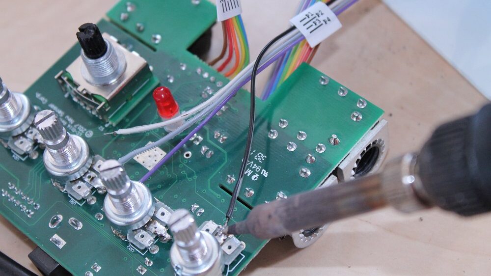
I hope you can find the potentiometers in the above circuit.
Pins of potentiometer
As you can see, a potentiometer is a three-terminal device. In practice, you should know which terminal is the slider and which ones are the fixed terminals.
In case you mistakenly connect the potentiometer the wrong way in your projects. Chances are your circuit may not work. Worse if the potentiometer is at the lowest value a high flow of current can damage your circuit board.
So, how to find the right pin configuration of a variable resistor?
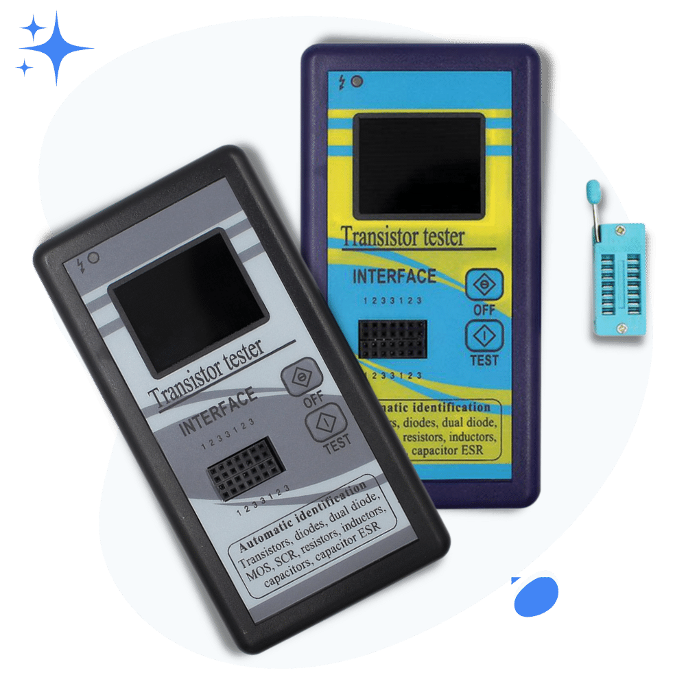
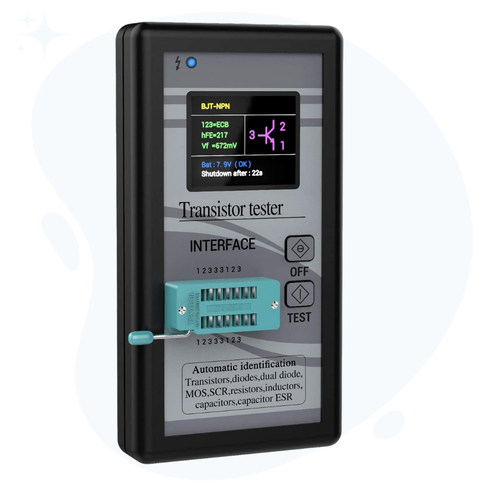
Well, for this we need to have a component tester like the M328 tester (product link).
Following is the picture of the component tester I have for testing various types of electronics and electrical components.
Follow the following simple steps to find out the pins of a potentiometer:
- Take your component tester and turn it on
- Take your potentiometer and connect it to the component tester
- By connecting I mean plugging the potentiometer into the socket of the tester
- After that, press the test button
- See the exact pin configuration on the screen of the tester.
Other than this method, you can use a multimeter as well. But at the beginner level using the multimeter is subjected to many errors. This method is more safe and easy to implement.
Potentiometer testing
The testing of the potentiometer is essential, what if you connect a potentiometer without testing if it works or not? If the potentiometer is damaged or short your project will not work.
Different tools are used to test a potentiometer, here is a detailed explanation of each tool and how to use it.
1. Testing using a multimeter
For testing a potentiometer we need a decent multimeter like this one (Amazon link).
Remember, a potentiometer has two fixed terminals, i.e., the resistance value between these two terminals does not change.
The remaining third terminal is the slider. Changing its position changes the resistance value.
Testing this type of resistor is very exciting.
First, take your multimeter and the potentiometer you want to test. Follow the following simple steps.
- Set the multimeter to resistance mode.
- We have two multimeter probes and three terminals of the potentiometer. Connect the probes to any of the two.
- Change the slider
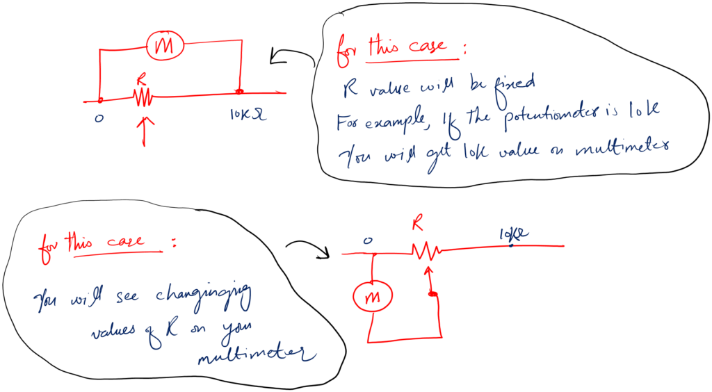
- If the value on the screen changes – this is your slider terminal. If not then the terminals are the fixed ones.
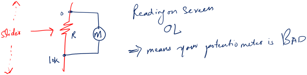
Case 1: Probes are connected to fixed terminals. You change the slider nothing happens.
But you see OL reading on screen. This means your potentiometer meter is open across the fixed terminals.
Case 2: Probes are connected to fixed terminals. You change the slider nothing changes.
And you have 0 reading on the screen. This means your potentiometer is short.
Case 3: Probes are connected to the slider terminal. You change the slider nothing happens. But you see OL reading on the screen.
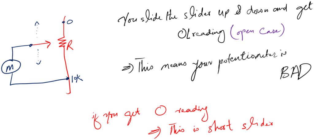
This means your slider terminal is open.
Case 4: Probes are connected to the slider terminal. You change the slider nothing happens. But you see 0 reading on the screen.
This means your slider terminal is short.
As a side note for hobbyists. If the slider is short and the fixed terminals are fine then use it as a fixed value resistor.
2. Testing using a component tester
While a multimeter just does the measurement and leaves the testing to the person’s knowledge and experience.
A component tester solves this problem. And tell you directly if the component is bad or good. Leaving the guesswork.
Following is the m328 component tester.
To use this mentioned tester for variable resistor testing, follow the following steps.
- Take your variable resistor and the m328 tester
- Turn on the tester and put the resistor in the socket
- Press test button
- See the resistance value if the resistor is fine
- Else the tester will show a message on the screen saying that the variable resistor is bad
It can not be simpler than this.
Mathematics of a potentiometer
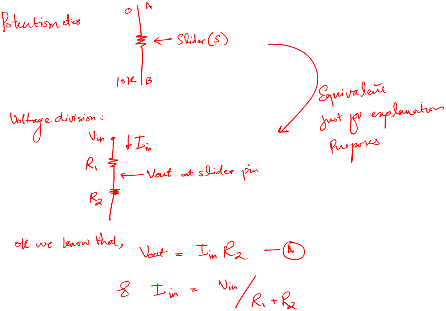
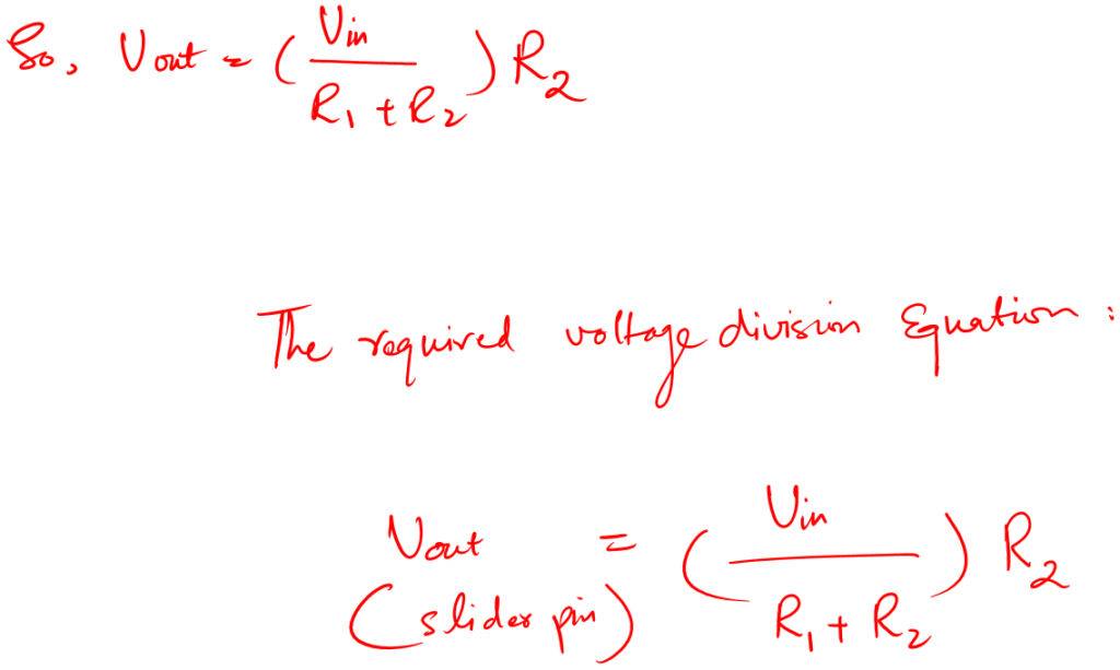
As we have learned by changing the slider position we change the resistance. This changed resistance varies the potential value. With this, we can say that a potentiometer meter is like a voltage divider.
The following is the simple math of finding the voltage division on the slider pin.
Why slider pin?
Because this is the only pin that physically changes.
We take output at the slider pin. Please always keep this in mind.
This changing potential is so important in many applications.
Let me share a few basic applications.
Applications of potentiometer
We have learned a lot of things about variable resistor basics.
Let’s see in what situation we should use a potentiometer in our circuit designs.
- We use a potentiometer as a voltage divider
- For frequency attenuation and tuning: Like a radio has so many channels to tune to. Variable resistance can help us select the frequency of our choice.
- For sounds increase and decrease
- For pulse width modulation
Conclusion
A variable resistor also known as a potentiometer is a three-terminal component that has adjustable resistance. By adjustable resistance I mean we can change its resistance value by moving one of the three terminals.
Among the three terminals, two terminals are a fixed-value resistor. One terminal is the slider. This slider moves over the fixed value resistor and thus gives us variable resistance values of our requirements.
These resistors come in various shapes and sizes. We work with one according to our circuit design parameters.
We use a potentiometer in our circuit for tuning, attenuation, and voltage divisions.
That is it. That is all I have for you above variable resistor basics. I hope you enjoyed my limited knowledge efforts.
Thank you and have a grateful life.
Other useful posts: