

Inductance Measurement Methods (Easy Guide 2026)
An inductor is a very fundamental circuit component that we use for noise filtering and energy storage in most of our circuits.
To properly use an inductor for circuits. We need to measure its inductance value so that we make sure we are using the right one according to the circuit design.
The question is, how to measure the inductance of a given inductor?
Well, this is what we will learn in this article.
At the end of this article, you should be able to know:
- Inductance measurement general theory
- Easy and particle inductance measurement methods
- Learning how to use an LCR meter
- How to work with function generator and oscilloscope for inductance measurements
Sounds interesting? Then, I am pretty positive you will enjoy the rest of this article as well.
Let’s get started.
Inductance measurement theory
You know, in real time circuits we encounter noise from internal components due to heat. We also get noise from the external environment as well.
We really can’t eliminate this noise by all means. But we can filter or suppress it to an acceptable level.
To achieve such an acceptable level, an inductor helps us a lot. It helps us get rid of the external noise coming into the circuit.
You may have seen some inductor in the very front of any device acting as a chock.
Before getting into the methods, I think we first need to make some background about them.
Why do I think so?
Because I think humans are very creative. You give them the knowledge, and they can do some amazing things with that knowledge.
Who knows, some of you may actually design a new way of measuring inductance.
Alright!
Basically, an inductor is a circuit component. It is a wire wound around some materials and has the capability of storing energy.
Following is the circuit symbol and some physical inductors:
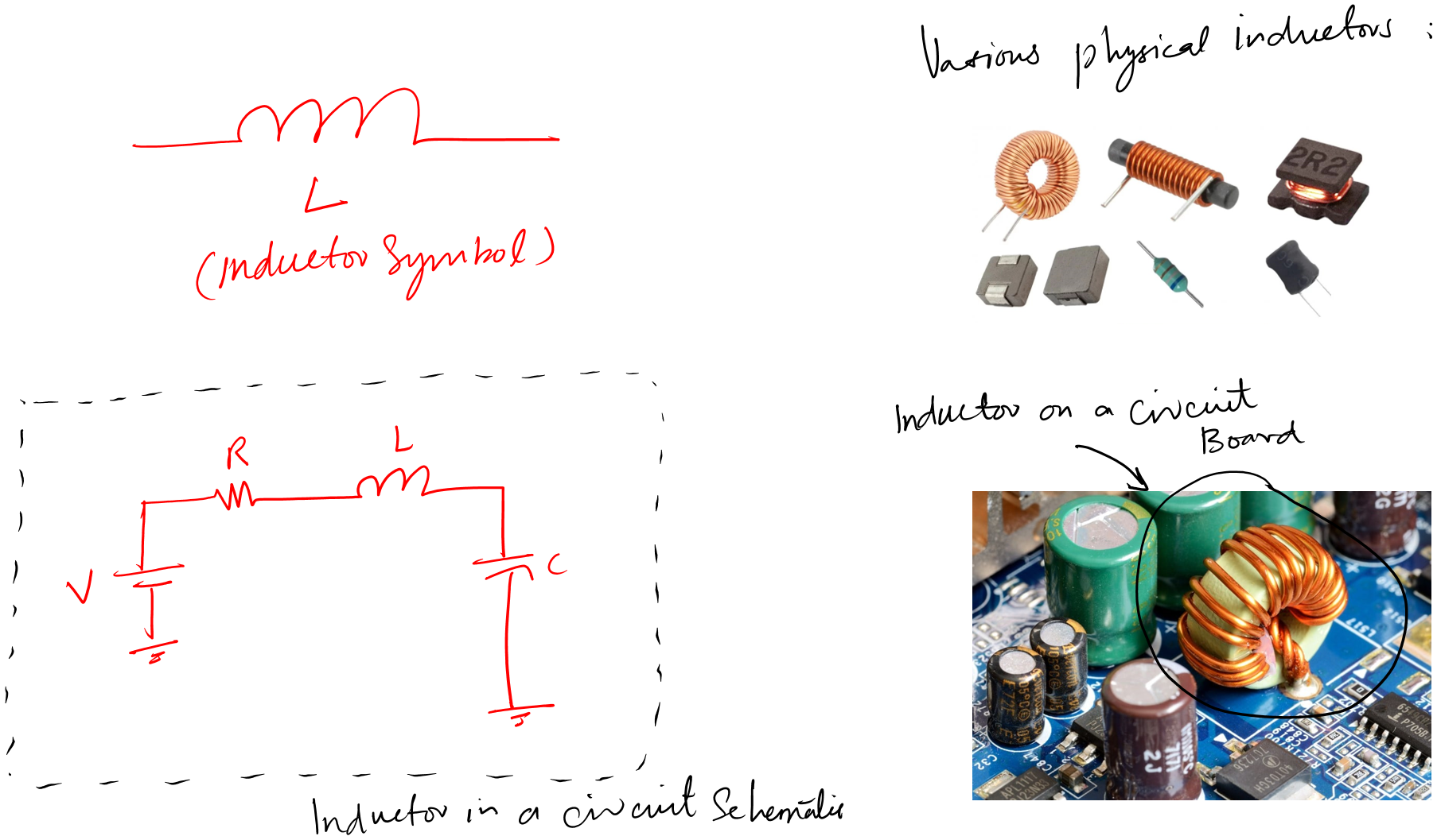
From the above picture, you can tell that it has two terminals. But this is not the case every time.
There are variable inductors as well.
A variable inductor is a type of inductor that has the capability of adjusting inductance values. For example, we can change its inductance value according to our circuit design.
Following is the circuit symbol of a variable inductor.
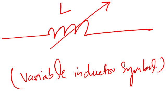
This inductor has three terminals. Two are fixed. While one is variable.
Using the variable terminal we can have any inductance value within the given range between the two fixed terminals.
No matter what the type of inductor we are interested in measuring its inductance.
But what is inductance? Is there any mathematics behind inductance that we can use to design our testing tool and procedure?
Let’s find out.
Inductance
An inductor is a circuit component. To measure its filtering and energy strong capability we need a proper term.
That term is inductance (L).
Inductance (L) is the ability of an inductor to store energy
The SI unit of inductance (L) is Henry (H).
So, the proper way to work with an inductor is to know about its inductance value.
This inductance value can also be interpreted as the opposite of an inductor to the current flow through it.
You know, no one like change. The same goes for an inductor as well. It doesn’t like its state to be changed. So it opposes that change through inductance.
Let’s see the very basics mathematics of an inductor:
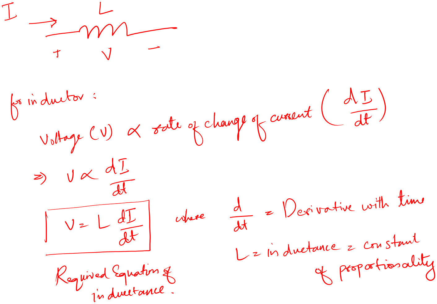
The equation is basically saying that an inductor has a voltage that equals the product of the time rate of change and inductance value.
Also, it means that the changing current induces a voltage across the given inductor.
The key thing is that the current must be changing.
But…
What if the current is constant like what if it is DC current?
Let’s see what the mathematics says about this:
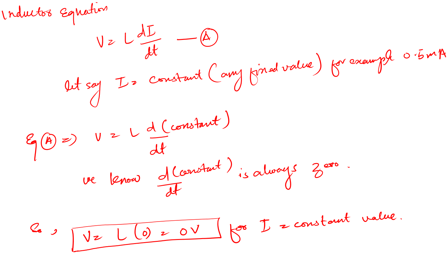
What this means is, that when the current is constant DC we would have zero voltage across the inductor.
In short, the inductor would act like a short circuit.
Let’s see what this means on the circuit level:
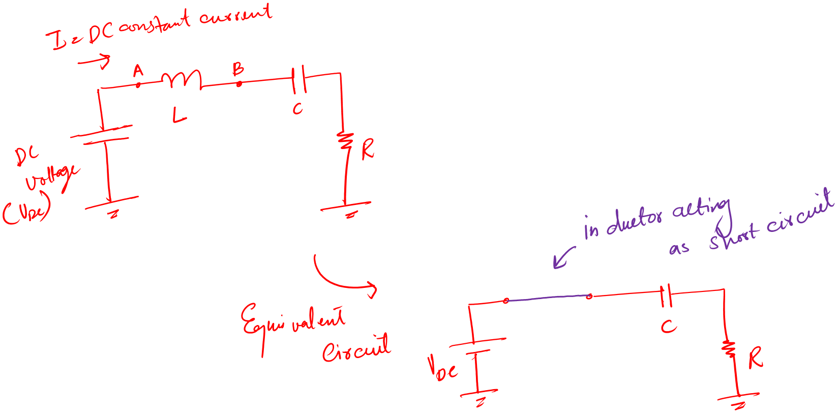
In a circuit, for DC constant current an inductor is like a piece of straight wire.
Hi, Enjoying the article so far?
If you are, I think you’ll find the ‘Measurements and Testing’ chapter of my book, Make Your First Electronic Circuit, incredibly helpful. It guides you step by step through measuring and testing all the fundamental electronic components in a simple and practical way. Check it out now!
Download your free sample of the chapter and start learning today!
Or, buy complete book
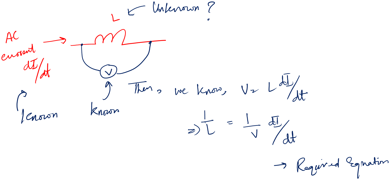
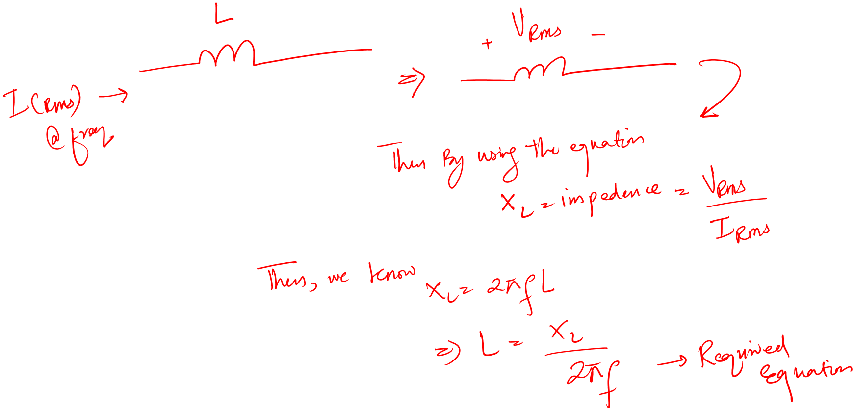
Keeping the inductance formula in mind, I can say that: If we apply an ac signal or current to the inductor and measure the voltage across it, then we can have inductance.
Another way to use the inductor reactance equation.
What is a reactance equation?
Basically, it is the resistance or impedance of the given inductor.
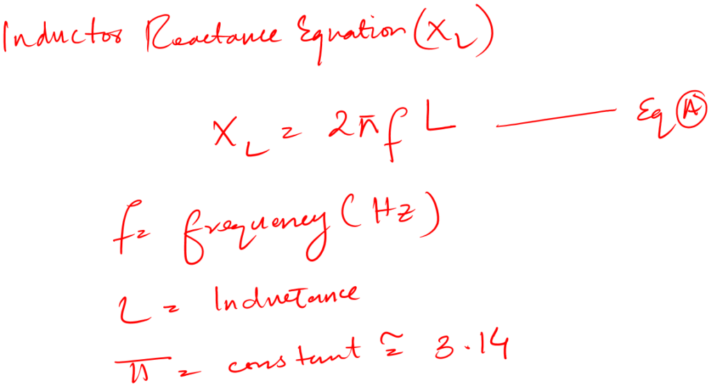
Now to use this equation: we would apply alternating current (RMS) of known frequency (F). This will induce a voltage across the inductor.
Then by dividing the voltage by the current will give us the impedance of that inductor.
Then by using the above equation we can easily calculate the value of inductance.
Let’s see the mathematics below:
You can now probably tell that there are many possible ways that one can think of and design a tool. Now, keep in mind some methods are good in theory, but they are not commercially applicable.
Inductance measurement methods
In practical work, you may need to measure inductance solo, or maybe you would require measuring inside the circuit board.
No matter what, the following are the methods that can help you.
Using LCR meter
First, let’s have a look at what is actually an LCR meter.
The word LCR is short for Inductance Capacitance Resistance. Meaning this is an electronic device that we use to measure these three mentioned parameters.
- In the R mode, it can be your resistance or OHM meter
- In the C mode, it will be capacitance and ESR meter
- In the L mode, it will be your inductance meter
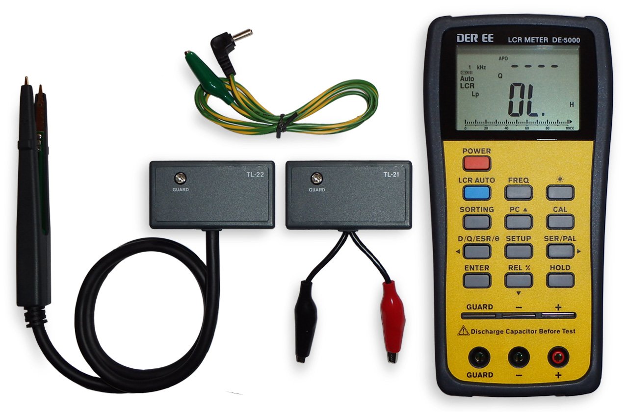
Follow the below easy steps to measure inductance.
- Take the LCR meter (Amazon link) and turn it on
- Take your inductor and connect it to the LCR meter
- Press the LCR Auto button on your meter
- And get the results on the screen
It is just that simple and easy.
Other than this method there are several ways. But I think this one is the most effective one.
Using a component tester
Let’s talk about another way of measuring the inductance of an inductor.
For this method, we would need a component tester with inductance measuring capability.
Basically, a component tester is an electronics tool that helps us find the:
- Correct pin configuration of various components like transistors, capacitors, and so many more.
- Help us test the component.
- By testing, I mean to tell if the component is good or bad.
- A component tester also helps us measure various component related parameters as well.
- For example, with a transistor, we not only get the correct pin configuration but also the DC best value as well.
Following is the picture of the component tester I have for testing various types of electronics and electrical components.
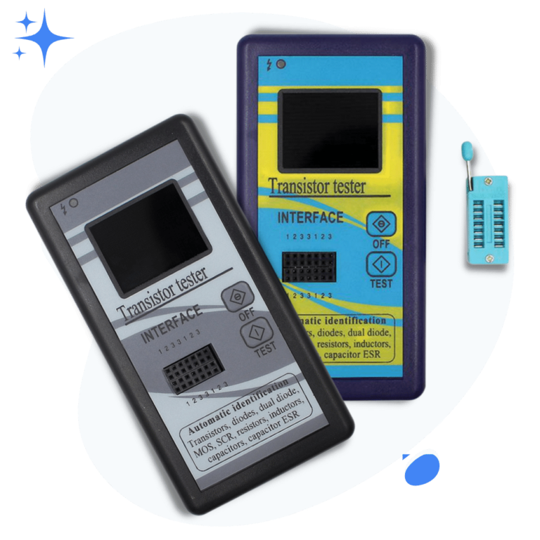
Alright! Let’s now see how to use it to measure the inductance of an inductor.
- Take your inductor and the component tester
- Turn on the tester and put the inductor in the socket
- Press test button
- See the inductance value if the inductor is fine
- Else the tester will show a message on the screen saying that the inductor is bad
It is that simple.
Now, if the component tester mentioned above has got you curious and wants to know more about it. Here is the link, M328 Component Tester (Amazon link), for your own further research and investigation.
Using an Oscilloscope
You can measure the inductance using an oscilloscope as well. But let me tell you right away, this is more technical than the above methods.
Also, it needs some calculations as well.
But it is fun if you enjoy working with electronic devices and instruments.
Let’s see how to measure an inductor using a digital oscilloscope.
For this method, we require a function generator as well.
First, let me quickly define these heavy names for beginners, and then we will proceed with our talk.
Oscilloscope:
An oscilloscope is a device that we use to measure or analyze changes in any electrical signal, and to study the behavior of a system, within its bandwidth limits.
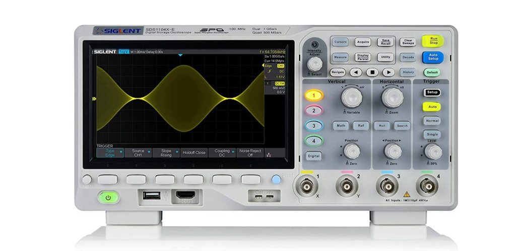
It displays an electrical signal with respect to time, so you can see every detail of the signal i.e., its shape, frequency, amplitude, and distortion.
Function generator:
A function generator is a device that we use to make various shape and amplitude signals for our circuits and projects.
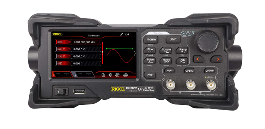
First, let me tell you that a function generator and a signal generator both represent the same device. So don’t get confused with it.
There is a slight difference there but at the beginner or hobbyist level, it doesn’t matter that much.
A signal generator is a device that generates electronic signals while a function generator has a preset list of waveforms or patterns that it can play.
So you can say that with the signal generator you can make any signal while with a function generator you have limited options to work with, but they are enough for a large scope of projects.
Alright with these two tools in the lab we can now measure inductance.
Follow the following steps:
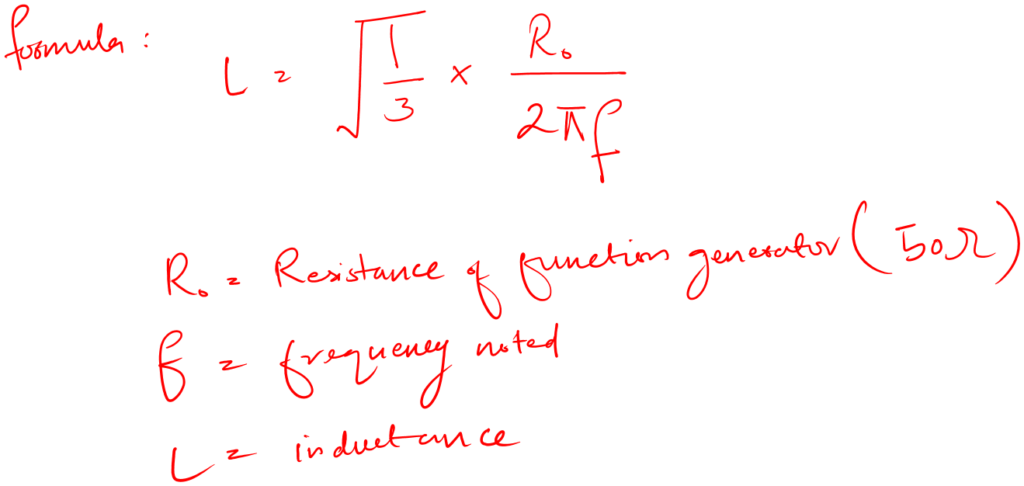
- Connect your oscilloscope, function generator, and your inductor in the form of the following circuit.
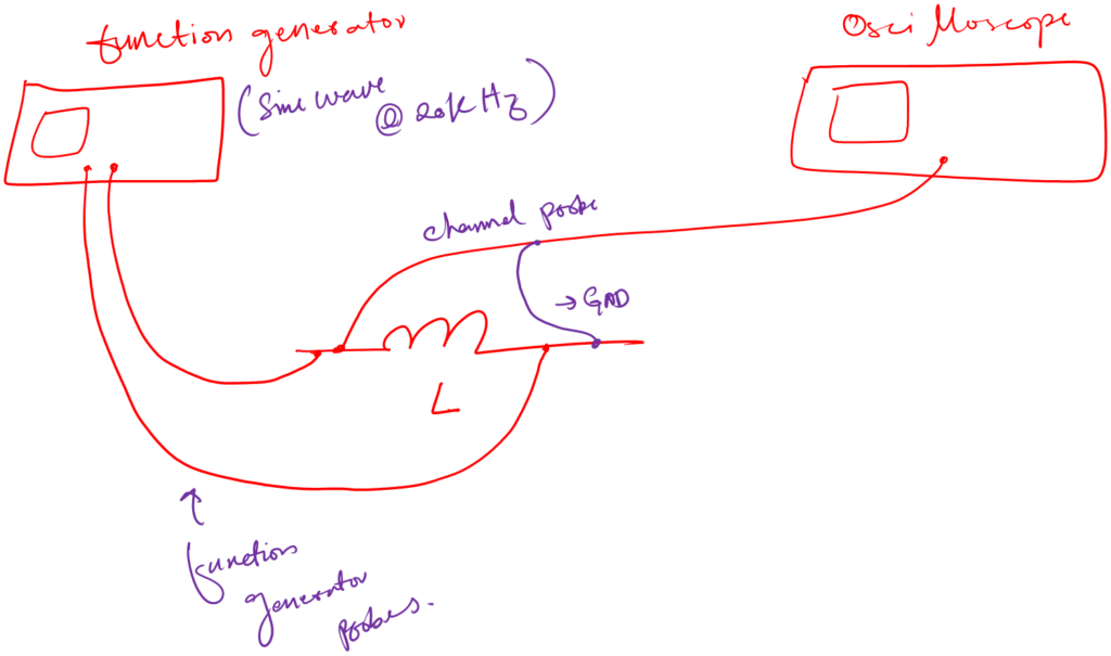
- Set the function generator at sin wave (3Vpp) with a frequency of 20kHz initially
- Now, keep decreasing the frequency to the level when you reach 1.5Vpp (exactly half of 3Vpp).
- 1.5Vpp will be on the oscilloscope screen.
- At this point, note down the frequency on the function generator.
- Put the values in the following equation and you have your inductance value.
You may feel like this method is more tedious than the above simple LCR or component tester.
Another thing to remember. Sometimes the output resistance of the function generator is not known. In such cases, you would need to first calculate that output resistance value before thinking of calculating the inductance value.
In the mentioned case:
Measure the unloaded voltage of your function generator with an oscilloscope. Then measure the loaded one with a resistor connected to your function generator. After that simply use the voltage division formula to get the output resistance value.
Why we can’t use a multimeter?
A multimeter is a tool that we use for a lot of measurements in our lab. As you saw above I didn’t use a multimeter in any method.
So why not?
The simple answer is the multimeter is not designed for such measurements.
Yes, we can use it for inductance measurements using resistance and reactance techniques. But I think, that is not effective. I don’t want to use formulas and other things to get single inductor measurements.
The method of using an oscilloscope and multimeter seems good on paper, but I don’t believe they are more effective when compared to LCR.
Imagine you work with 10 20 inductors at a time. Then oscilloscope and multimeter would be a nightmare for you. Like first finding the frequency, then using a scientific calculator to actually calculate the inductance.
Let’s not forget how much prone these methods are to human errors as well.
Conclusion
An inductor is a two terminal passive circuit element that we use for noise cancellation and frequency tuning. We sometimes also use it as an energy storing component that has the ability to provide instant current for our circuit.
Basically, it is a wire wound around some materials.
Now this wire can be wounded in a cylinder shape or circle shape.
We measure inductors in terms of inductance. And the SI unit of inductance in Henry (H). Inductance tells us about the energy storing and noise filtering capability of the given inductor despite of whether the inductor is fixed or variable.
To measure inductance we use an LCR meter. And for testing, if the indicator is good or bad we use a component tester.
Besides these measuring methods, you can use an oscilloscope. But I don’t think using an oscilloscope is an easy method for beginners.
As an oscilloscope method requires some circuit building and intense mathematical calculations. You should do it when you don’t have access to an LCR meter.
Please be sure that the inductor is charge free. Like it should not have any precharge stored. Else it can damage your testing device. And also harm you.
Alright!
That is it. That is all I have for you about inductance measurement methods for beginners. I hope you enjoyed it.
Thank you and have a grateful life.
Other useful posts: