

Inductor Basics: Everything beginner must know (2026)
The inductor component feels like a hard component to learn or to work with. But let me tell you I think this is some kind of common feeling for almost beginners.
An inductor is a basic electronic component that stores energy in its magnetic field when electrical current flows through it. It typically consists of a coil of wire wound around a core, which can be made of air, ferrite, or another material. They are useful in filtering, tuning, and energy storage applications in circuits. Their behavior is characterized by inductance, measured in henries (H), which depends on the number of turns in the coil, the core material, and the coil’s dimensions.
In this article, we’ll learn about inductor basics, simple definitions, the circuit symbol, and how we use and test an inductor.
Inductor basics
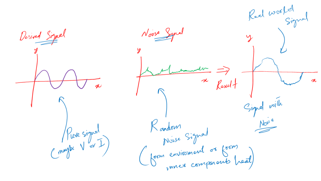
You know, to work in electronics it is ideally required to have smooth and noise-free voltages, currents, and other signals.
But in reality, this is not the case.
In reality, we get a lot of noise in our voltages and signals.
Some noise is added by the circuit components due to heat. Another noise is added from the environment or other nearly placed electronic devices.
We can not eliminate the noise. But we can decrease its level to our working requirements.
For such situations we use inductors.
1. Definition
In understanding basics of electronics properly, we define an inductor like:
An inductor is a circuit component that has the capability to eliminate noise, and filter signals, frequency tuning, and is sometimes used as an energy storing component.
Frequency tuning can be understood by using the example of a radio. In radio, we tune to different frequency stations.
This station selection is done by using inductors in the backend electronic circuits.
Now besides filtering, an inductor has the capability to store energy as well. This energy can be taken by the circuit in the form of a current.
So, we can say that the inductor is like an instantaneous current-giving component in the circuit. It also means that when we work with these components, we must be careful as they may contain stored energy.
Circuit symbol
A circuit symbol is a unique symbolic representation of any given component. Each component has its circuit symbol.
These symbols help us draw circuits on paper as well as in simulation software.
The circuit symbol for an inductor is the following.
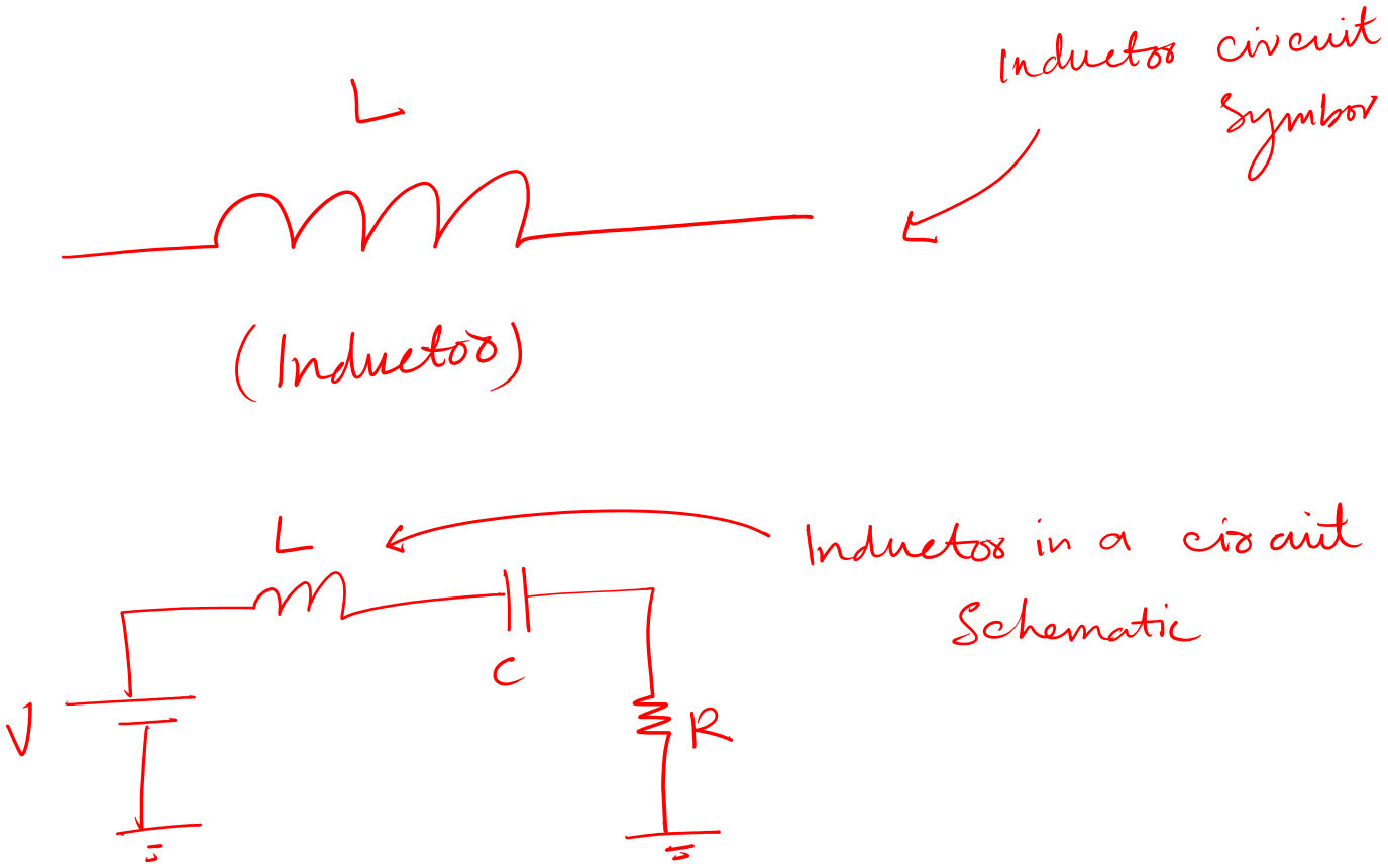
You can see that it has two terminals.
The good thing about an inductor is, it is non-polar. Meaning that there is no positive and negative terminal.
You can connect them in the circuit in any way you like.
Now, you can not say in general that an inductor must have three terminals. Because some types of inductors have more than two terminals.
Such as a variable inductor.
2. Variable inductor
This is a type of inductor that has the capability of adjusting inductance values. For example, we can change its inductance value according to our circuit design.
Following is the circuit symbol of a variable inductor.
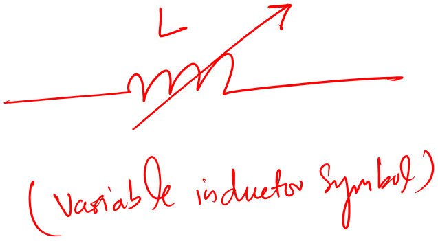
This inductor has three terminals. Two are fixed while one is variable.
Using the variable terminal we can have any inductance value within the given range between the two fixed terminals.
3. Inductor on circuit boards
I love this section. Here we can see what an inductor looks like physically.
The main focus of this section is to make a student able to spot an inductor in a circuit schematic as well as in a real circuit board.
The following are examples for your reference.
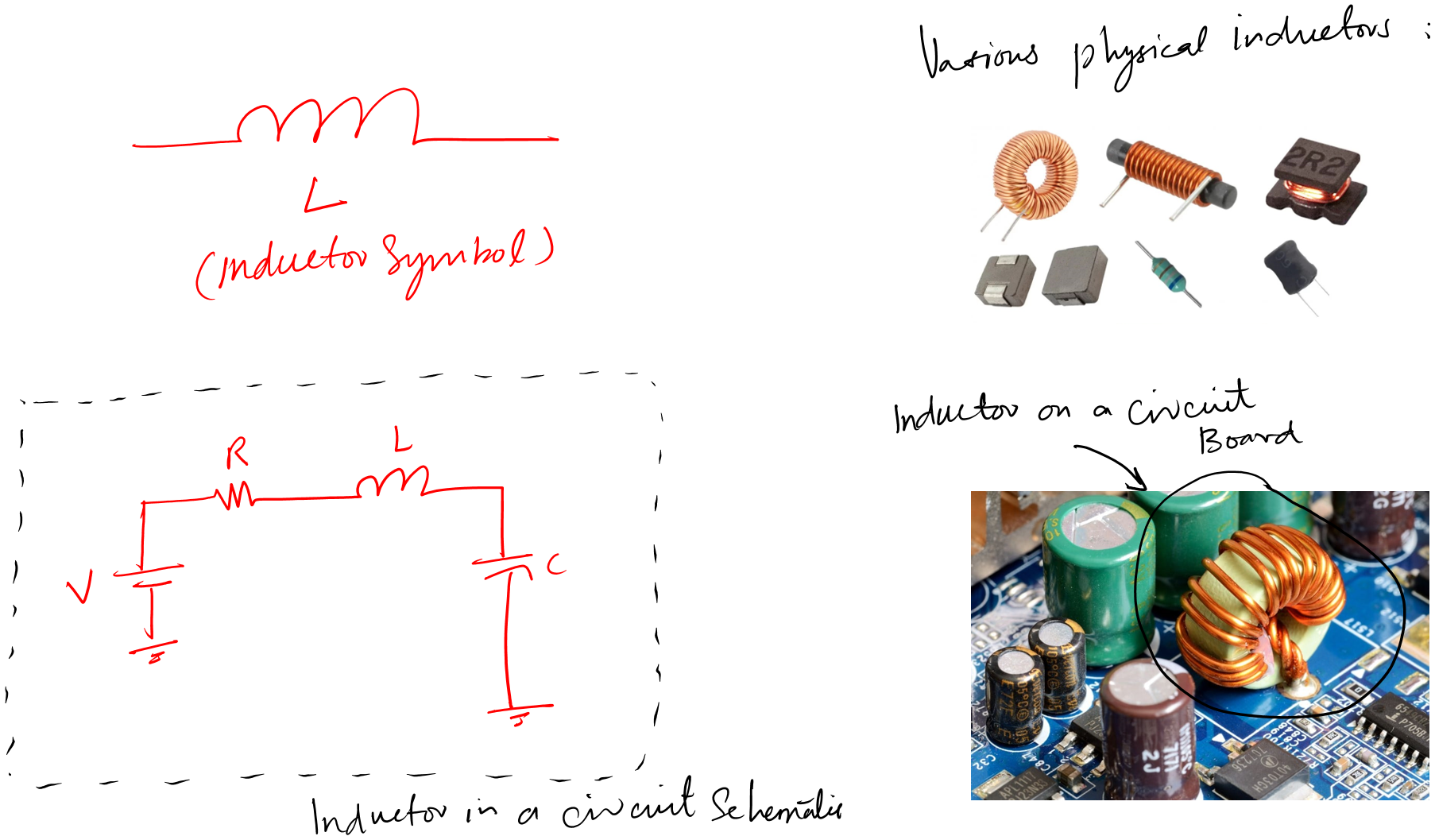
You can see that inductors come in various shapes and packages.
The key thing is that it is always a wire wound around something. Keep this in mind, and you may never miss an inductor in any given circuit board.
4. Inductance
An inductor is a circuit component. To measure its filtering and energy-strong capability we need a proper term.
That term is inductance.
Inductance is the ability of an inductor to store energy
The SI unit of inductance (L) is Henry (H).
So, the proper way to work with an inductor is to know about its inductance value.
This inductance value can also be interpreted as the opposite of an inductor to the current flow through it.
You know, no one likes change. The same goes for an inductor as well. It doesn’t like its state to be changed. So it opposes that change through inductance.
Mathematics of inductance
Let’s see the very basic mathematics of an inductor:
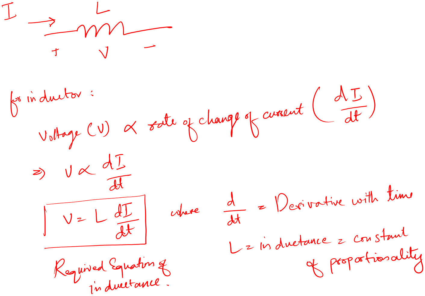
The equation is saying that an inductor has a voltage that equals the product of the time rate of change and inductance value.
Also, it means that the changing current induces a voltage across the given inductor.
The key thing is that the current must be changing.
But…
What if the current is constant like what if it is DC current?
Let’s see what the mathematics says about this:
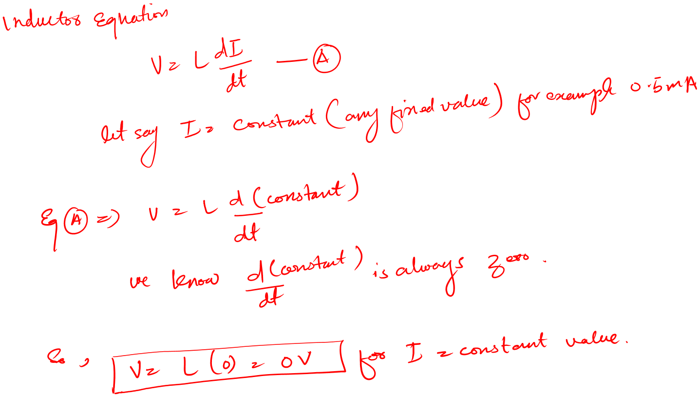
What this means is, that when the current is constant DC we would have zero voltage across the inductor.
In short, the inductor would act like a short circuit.
Let’s see what this means on the circuit level:
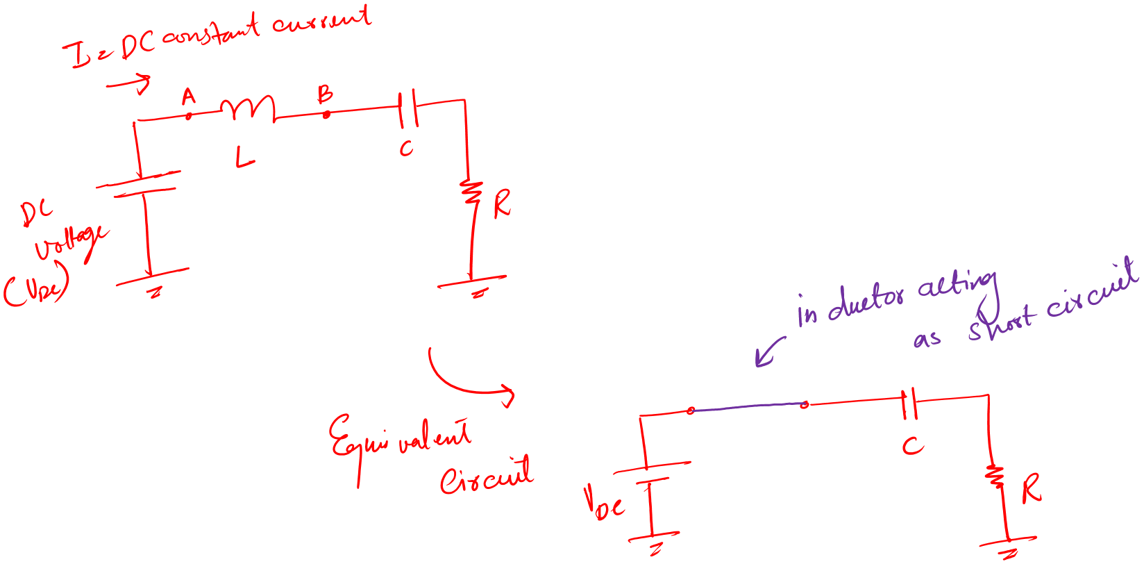
In a circuit, for DC constant current an inductor is like a piece of straight wire.
Inductance measurements
The inductance of an inductor is measured in Henry (H). To use an inductor in our circuit we need to measure this inductance value.
Because the inductance value in our circuits is according to our requirements. We need to verify the exact value of the inductor before we use it in our circuit.
So how do we do that?
Well, the answer is simple: by using an LCR meter.
a. Inductance measurement using an LCR meter
First, let’s have a look at what is an LCR meter.
The word LCR is short for Inductance Capacitance Resistance. This is an electronic device that we use to measure these three mentioned parameters.
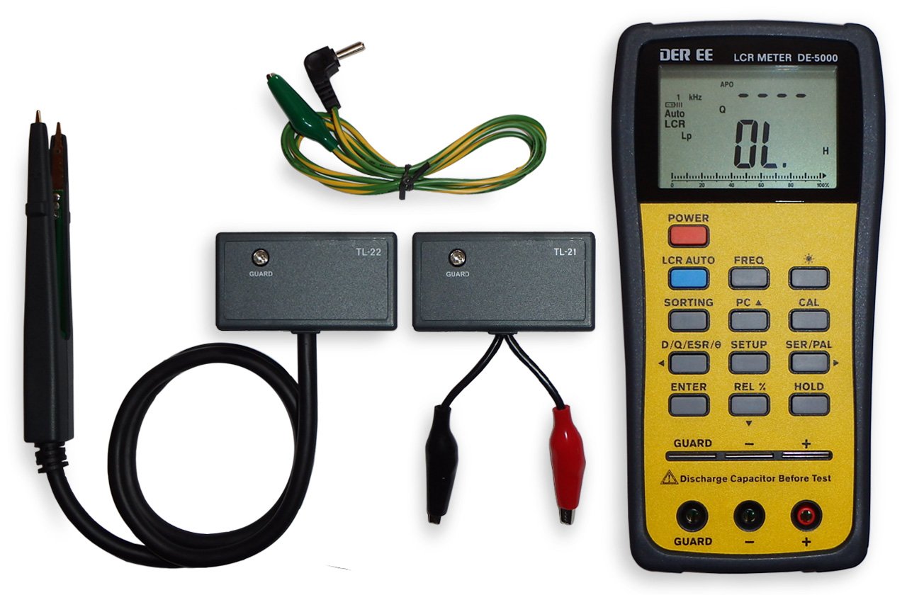
Follow the below easy steps to measure inductance.
- Take the LCR meter (Amazon link) and turn it on
- Take your inductor and connect it to the LCR meter
- Press the LCR Auto button on your meter
- And get the results on the screen
It is just that simple and easy.
Other than this method there are several ways. But I think this one is the most effective one.
Alternative methods include:
- Using an oscilloscope
- Using a function generator and various multimeter
Inductor testing
In learning inductor basics, I think testing is very important. Because if you put a bad inductor in your real circuit. It can damage that circuit. And we can take this risk. As circuits are expensive.
Inductor testing is necessary when you work in electronics repair. And your job is to work with old circuits.
So how we can test an inductor?
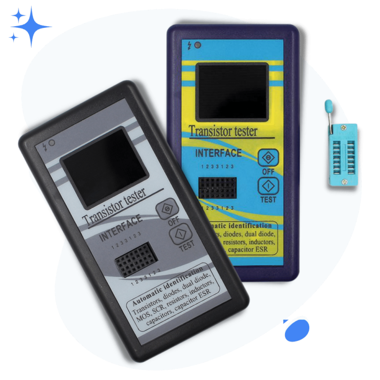
Simply, by using a component tester.
Just for beginners who don’t know what a component tester is. A component tester is an electronics tool that helps us find the:
- Correct pin configuration of various components like transistors, capacitors, and so many more.
- Help us test the component.
- By testing, I mean to tell if the component is good or bad.
- A component tester also helps us measure various component-related parameters as well.
- For example, with a transistor, we not only get the correct pin configuration but also the DC best value as well.
Following is the picture of the component tester I have for testing various types of electronics and electrical components.
Alright! Let’s now see how to test an inductor with a component tester.
- Take your inductor and the component tester
- Turn on the tester and put the inductor in the socket
- Press test button
- See the inductance value if the inductor is fine
- Else the tester will show a message on the screen saying that the inductor is bad
It is that simple.
Now, if the component tester mentioned above has got you curious and wants to know more about it. Here is the link, M328 Component Tester (Product link), for your own further research and investigation.
Why do we use inductors in our circuits?
This is an important question to ask. The answer will help you to make the right decisions about the inductor in your circuit design projects.
Well, we use inductors for the following main reasons:
- Noise cancellation
- Tuning
a. Noise cancellation
Noises are the unwanted signals suppressed upon the want or desired signal in a circuit.
We don’t want noise in a circuit at all, but we can’t eliminate it. We can do our best to reduce it to acceptable levels depending on the circuit’s output requirements.
What noise does is – it makes our circuit not work properly. If the level of noise goes beyond the acceptable level, it can damage our circuit or system completely.
To eliminate noise, we use inductors in our circuits. We usually place them right exactly where the signals enter our circuit boards as chokes.
b. Tuning
You know, generally speaking, tuning means to select or focus on a required frequency signal.
Tuning is the term used in communication. For example, radio. Now, there are many radio stations out there operating and broadcasting at certain frequencies. We tune our radio receiver set to listen to what we like.
We know that the back-end electronics circuit is responsible for this tuning operation. And inductors are key components of these circuits.
For tuning purposes, we use variable inductors, i.e., an inductor of variable inductance.
Changing the inductance values helps select or tune to a new frequency within the available spectrum.
Conclusion
An inductor is a two-terminal passive circuit element that we use for noise cancellation and frequency tuning. We sometimes also use it as an energy-storing component that has the ability to provide instant current for our circuit.
It is a wire wound around some materials.
We measure inductors in terms of inductance. And the SI unit of inductance in Henry (H).
To measure inductance we use an LCR meter. And for testing, if the indicator is good or bad we use a component tester.
Alright!
That is it. That is all I have for you about inductor basics for beginners. I hope you enjoyed it.
Thank you and have a grateful life.
Other useful posts: